Download
1 / 32
320 likes | 567 Views
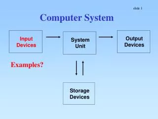
Input Devices. Microphone Symbol: Energy Change: sound electrical Solar Cell Symbol: Energy Change: light electrical. +. -. Thermocouple Symbol: Energy Change: heat electrical The higher the temperature at the junction, the more heat energy converted to electrical.

E N D
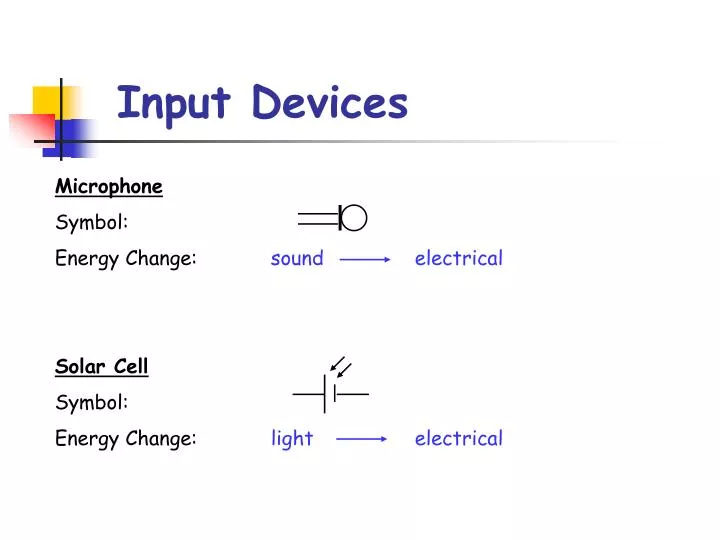
Input Devices Microphone Symbol: Energy Change: soundelectrical Solar Cell Symbol: Energy Change: lightelectrical
+ - Thermocouple Symbol: Energy Change: heatelectrical The higher the temperature at the junction, the more heat energy converted to electrical.
The Thermistor A thermistor is a special type of resistor whose resistance changes with temperature. Symbol:
Ω Experiment A thermistor is connected to an ohmmeter as shown. The resistance of the thermistor is measured by the digital ohmmeter at several different temperatures. Results Resistance of thermistor at hand temperature = Ω Resistance of thermistor at room temperature = Ω Resistance of thermistor at 0 °C = Ω
T U R D Conclusion As the temperature increases the resistance . As the temperature decreases the resistance will . decreases increase temperature up, resistance down
Light Dependent Resistor (LDR) A light dependent resistor (LDR) is a special type of resistor whose resistance changes with light intensity (brightness). Symbol:
Ω Experiment A thermistor is connected to an ohmmeter as shown. The resistance of the LDR is measured by the digital ohmmeter in bright light and in darkness (covered up). Results Resistance of LDR in bright light = Ω Resistance of LDR in darkness = Ω
L U R D Conclusion As the light intensity increases the resistance . So as the light intensity decreases the resistance will . decreases increase light up, resistance down
A Thermistor and LDR Problems A thermistor is connected to an ammeter and a supply voltage of 12 volts as shown. 12 V T (a) Calculate the reading on the ammeter at 20 °C. (b) Calculate the reading on the ammeter at 100 °C. (c) The reading on the ammeter at 150 °C will be: (i) 20 mA (ii) 30 mA
Solution (a) (b) (c) TURD – temperature goes up so resistance will go down. Smaller resistance means bigger current. Current will be 30 mA (0.03 A)
A A light dependent resistor (LDR) is connected to an ammeter and a supply voltage of 10 volts as shown. 10 V Calculate the reading on the ammeter at a light intensity of (a) 100 units (b) 500 units.
Solution (a) (b)
Yellow Book Thermistors and LDR’s – Page 47 Q25, Q26, Q27
The Capacitor A capacitor is an input device which introduces a time delay before something happens. Symbol: A capacitor is able to store charge. It takes a certain amount of time for an uncharged capacitor to charge up. Capacitance is measured in farads (F). A large value capacitor (e.g. 1000 μF) takes longer to charge up than a smaller capacitor (e.g. 200 μF).
Converting Units 1. Convert 150 μF into farads. OR You may leave in scientific notation. 2. Convert the following into farads: (a) 750 μF (b) 10 μF (c) 1500 μF 750 x 10-6 F 0.00075 F 10 x 10-6 F 0.00001 F 1500 x 10-6 F 0.0015 F
S 6 V R V 1000 μF 0 V Charging a Capacitor Experiment An uncharged capacitor is placed in a circuit as shown. Switch S is closed. The capacitor starts to charge up. The voltage across the capacitor is measured every 5 s after switch S is closed.
Results 0 0 5 10 120 A graph of the results was plotted:
The time it takes to charge a capacitordepends upon the size of: CAPACITOR it takes longer to charge a biggercapacitor RESISTOR it takes longer to charge with a bigger resistor (this is because the current is smaller) ** Need to know these factors affect time to charge capacitor **
VS R2 R1 V1 0 V Potential Divider This is an input device which consists of two resistors in series. The resistors divide the voltage supply into two parts. To calculate V1: To calculate V2: ** NOT on data sheet **
V2 V1 Example 1 In a potential divider circuit, a 6 volt supply is connected to two resistors as shown. 6 V 250 Ω Calculate the size of the voltage across each resistor. 500 Ω 0 V
The size of V2 is found by: • Points to Note: • V1 + V2 = VS • The BIGGER RESISTOR gets the BIGGER SHARE of the voltage supply. • If it is twice as big it gets twice as many volts etc.
V2 V1 Example 2 In a potential divider circuit, a 10 volt supply is connected to two resistors as shown. 10 V 1 kΩ Calculate the size of the voltage across each resistor. 4 kΩ 0 V
V1 Example 3 A 2 kΩ and 7 kΩ resistor are connected in a potential divider circuit as shown. 5 V 7 kΩ Calculate the size of the voltage V1. 2 kΩ 0 V
5 V V2 7 kΩ 2 kΩ 1.11 V 0 V The size of V2 is found by:
Yellow Book Potential Dividers – Page 46 Q18, Q19, Q20, Q21, Q22
V1 6 V 10 kΩ 1 kΩ 0 V Comparing Calculated Values Experiment The calculated value of V1 will be compared to the measured value using a voltmeter. Calculation
Experimentally The circuit shown was built and the voltage across the 1 kΩ is measured using a voltmeter. voltmeter reading = V Extension Reverse the positions of the two resistors and repeat experiment.
What Input Device? • Selecting Input Devices • If a TIME DELAY is involved – use a CAPACITOR. • In other cases – think carefully about the energy change.
Example 1 Choose a suitable input device from the following list for each application given: (GENERAL) microphone; thermocouple; solar cell; thermistor; LDR; capacitor (a) energy source for a satellite (b) time delay for arming a burglar alarm to allow householder out front door (c) temperature control for an aquarium (d) alarm warning parents in another room that baby is crying (e) measurement of temperature inside a blast furnace (f) circuit to reduce brightness of TV screen when room lights are switched off. solar cell capacitor thermistor mic thermocouple LDR
Example 2 Give a suitable input device for each application: (a) coin detector in a drinks machine (b) fog detector (c) heartbeat monitor (d) circuit switching hand drier on for 10 seconds (e) flame sensor for a gas fire (CREDIT) LDR LDR microphone capacitor thermocouple
(CREDIT) Questions Q1. Name an appropriate input device for the following applications: (a) automatic light switching on when light level becomes dim (b) heating system to switch on when temperature falls below 20°C (c) baby monitor detecting noises made (d) energy saving light system that switches lights on in hotel staircase for a time if 60 seconds (e) alternative energy source used in many calculators. LDR thermistor microphone capacitor solar cell