Download
1 / 28
280 likes | 317 Views
Learn engineering design analysis and different class model types, with a focus on UML class and object diagram notations and rules. Understand when to use these diagrams for effective software engineering analysis.

E N D
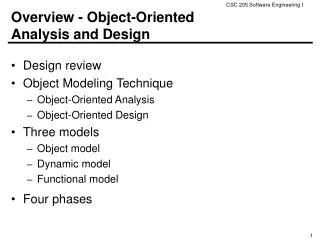
Objectives • To summarize engineering design analysis • To distinguish different types of class models • To present UML class and object diagram notations • To present class and object diagram rules and heuristics • To explain when to use class and object diagrams
Topics • Software engineering analysis • Class and object models • Classes and objects • UML class diagrams • UML object diagrams
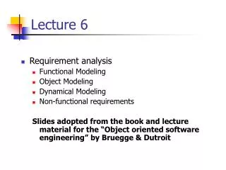
Analysis Goals, Inputs, and Activities • Understand an engineering design problem using • SRS • Product design models • Achieve understanding by • Studying the SRS and design models • Making analysis models
Analysis Models • Both static and dynamic models • Object-oriented and other kinds of models An analysis model is any representation of a design problem.
Class and Object Models • Class (object) diagrams are graphical forms of class (object) models. • Other forms are possible, such as CRC cards. A class (object) model is a representation of classes (objects ) in a problem or a software solution.
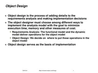
Types of Class Models • Analysis or conceptualmodels—Important entities or concepts in the problem, their attributes, important relationships • Design class models—Classes in a software system, attributes, operations, associations, but no implementation details • Implementation class models—Classes in a software system with implementation details • Analysis models represent the problem; design and implementation models represent the solution.
Classes and Objects • An object is an entity that holds data and exhibits behavior. • A class is an abstraction of a set of objects with common operations and attributes. • An attribute is a data item held by an object or class. • An operation is an object or class behavior. • An association is a connection between classes representing a relation on the sets of instances of the connected classes.
UML Names • A name in UML is character string that identifies a model element. • Simple name: sequence of letters, digits, or punctuation characters • Composite name: sequence of simple names separated by the double colon (::) • Examples • Java::util::Vector • veryLongNameWithoutPunctuationCharacters • short_name
UML Class Symbol • Compartments • Class name • Attributes • Operations • Other compartments • Compartment order • Suppressing compartments • Class name compartment must contain a name (simple or composite)
Attribute Specification Format name : type [ multiplicity ] = initial-value • name—simple name, cannot be suppressed • type—any string, may be suppressed with the : • multiplicity—number of values stored in attribute • list of ranges of the form n..k, such that n <=k • k may be * • n..n is the same as n • 0..* is the same as * • 1 by default • if suppressed, square brackets are omitted • initial-value—any string, may be suppressed along with the =
Operation Specification Format name( parameter-list ) : return-type-list • name—simple name, cannot be suppressed • parameter-list • direction param-name : param-type = default-value • direction—in, out, inout, return; in when suppressed • param-name—simple name; cannot be suppressed • param-type—any string; cannot be suppressed • default-value—any string; if suppressed, so is = • return-type-list—any comma-separated list of strings; if omitted (with :) indicates no return value • The parameter-list and return-type-list may be suppressed together.
Association Lines • Labeled or unlabeled lines • Readable in two directions • Direction arrows • Rolenames
Association Multiplicity The multiplicity at the target class end of an association is the number of instances of the target class that can be associated with a single instance of the source class.
Class Diagram Rules • Class symbols must have a name compartment. • Compartments must be in order. • Attributes and operations must be listed one per line. • Attribute and operation specifications must be syntactically correct.
Class Diagram Heuristics 1 • Name classes, attributes, and roles with noun phrases. • Name operations and associations with verb phrases. • Capitalize class names only. • Center class and compartment names but left-justify other compartment contents.
Class Diagram Heuristics 2 • Stick to binary associations. • Prefer association names to rolenames. • Place association names, rolenames and multiplicities on opposite sides of the line.
Class Diagram Uses • Central static modeling tool in object-oriented design • Conceptual models • Design class diagrams • Implementation class diagrams • Can be used throughout both the product and engineering design processes
Object Diagrams • Object diagrams are used much less often than class diagrams. • Object symbols have only two compartments: • Object name • Attributes (may be suppressed)
Object Name Format object-name : class-name[ stateList ] • object-name—simple name • class-name—a name (simple or composite) • stateList—list of strings; if suppressed, the square brackets are omitted • The object-name and class-name may both be suppressed, but not simultaneously.
Object Attribute Format attribute-name = value • attribute-name—simple name • value—any string • Any attribute and its current value may be suppressed together.
Object Links • Show that particular objects participate in a relation between sets of objects • Instances of associations • Shown using a link line • Solid line (no arrowheads) • Underlined association name • Link lines never have multiplicities
Object Diagram Uses • Show the state of one or ore objects at a moment during execution • Dynamic models as opposed to class diagrams, which are static models
Summary 1 • Engineering design begins with analysis of the SRS and product design models. • Analysis modeling helps designers understand the design problem. • Class models include analysis (conceptual), design, and implementation class models.
Summary 2 • UML class diagrams can be used for all types of class models, and throughout the design process. • UML object diagrams represent the state of objects during execution.