Download
1 / 15
150 likes | 255 Views
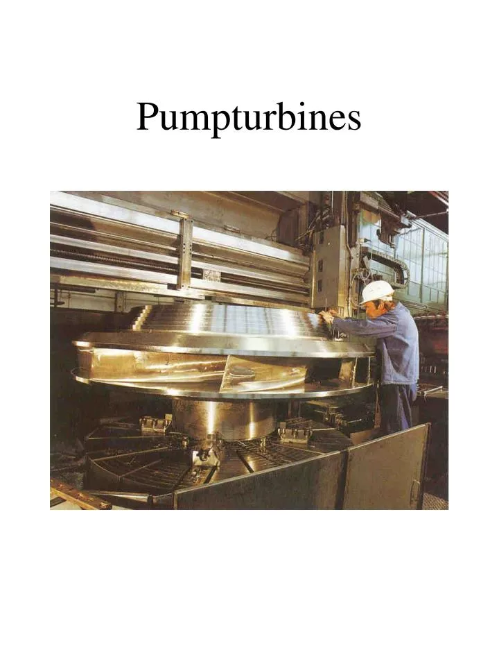
Pumpturbines. 1. 3. 4. 2. 5. 2-3:. Turbine mode. 1-2:. 3-4:. 4-5:. 1. 3. 4. 2. 5. Turbine mode. 1. 3. 4. 2. 5. 3-2:. Pump mode. 5-4:. 4-3:. 2-1:. 1. 3. 4. 2. 5. Pump mode. 1. 3. 4. 2. 5. Pump versus turbine mode. Euler’s equation for pump and turbine. 1. 2.

E N D
1 3 4 2 5 2-3: Turbine mode 1-2: 3-4: 4-5:
1 3 4 2 5 Turbine mode
1 3 4 2 5 3-2: Pump mode 5-4: 4-3: 2-1:
1 3 4 2 5 Pump mode
1 3 4 2 5 Pump versus turbine mode
Hnp> Hstbecause of the head loss Specific energy turbine mode: Ent = g·Hnt Specific energy pump mode: Ept = g·Hnp Static pressure (Q=0): Hst Theoretic head (turbine mode): Htt Theoretic head (pump mode): Htp Hnt< Hst because of the head loss
We assume: Frictionless flow Hnt = Hnp No swirl at the outlet (turbine mode) Cu2 = 0 For the turbine the Euler equation can be written as: For the pump:
We assumes that: Speed is the same in both turbine and pump mode (u1is the same for both pump and turbine) From the equations we can derive: This means:
For a pump turbine the following yields: • Hnt < Hnp • We can not achieve no swirl condition in both turbine and pump mode on the low pressure side (inlet of the pump and outlet of the turbine) • The equation above show that the pump turbine has to be designed for a higher head than the theoretical head. • The pump will be designed with the assumption: u1= 0,95
Bajina Basta, Yugoslavia D0 = 5,6 m De = 4,7 m Di = 2,2 m B0 = 0,31 m Turbine mode: *Q = 61,8 m3/s *H = 554 m *P = 294 MW Pump mode: *Q = 41,8 m3/s *H = 602 m *P = 281 MW