Download
1 / 12
0 likes | 10 Views
The thermal processes used in the Zero Liquid Discharge Systems generally use the following two unit operations.<br>For more info please visit https://watermanaustralia.com/agitated-thin-film-evaporators-dryers-involved-in-zero-liquid-discharged-zld-system/

E N D
Email Address water@watermanaustralia.com AGITATED THIN FILM EVAPORATORS/DRYERS INVOLVED IN ZERO LIQUID DISCHARGED (ZLD) SYSTEM – A COMPARATIVE STUDY Home » Blogs on Water Treatment Plant & Machinery » Agitated Thin Film Evaporators/Dryers involved in Zero Liquid Discharged (ZLD) System – A Comparative Study Agitated Thin Film Evaporators/Dryers involved in Zero Liquid Discharged (ZLD) System – A Comparative Study WATERMAN ENGINEERS AUSTRALIA Zero Liquid Discharge System Water is by far the most important commodity in today’s industrialized world. However, its increased use and contamination in industrial processes have put great threats to both its scarcity and environmental pollution. With such an alarming consequence, coming up with an idea like the “Zero Liquid Discharge System” or ZLD System that can effectively address the issues of water quality, security, ecosystems, and economic growth as well. In the Zero Liquid Discharge (ZLD) technique, we generally focus on minimizing the waste and recycling the
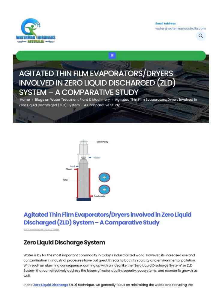
water without discharging it to the receiving bodies. In the conventional ZLD systems, we focus on the thermal processes, i.e., feeding the wastewater (brine) into evaporators and then to brine crystallizers of zld water treatment plants. The distillate then gets recycled in an effluent recycling system. While the rest of the solids are either disposed of or recovered as valuable by-products in the downstream processes of zero discharge system. As best zld suppliers, a typical ZLD system which is the most widely used includes the main components (evaporator/crystallizers system) as shown in figure 1. The pre-treatment of the wastewater generally includes pH adjustment, filtration, and de-aeration. Some of the anti-scaling agents are also added for the safe operation of the downstream equipment and for good heat transfer as well. Then the product is successively evaporated in the brine concentrator (evaporator) and brine crystallizer for its reuse in the industry. However, we can recover the solids or dispose them of depending upon the susceptibility of whichever situation is economical. Advantages of the Zero Liquid Discharge System (ZLD) We can use the ZLD system or Zero Liquid Discharge Systems. to recover valuable substances and sell them in the market to make it an economical process as well. We can obtain a 5099 % concentrated caustic soda through the ZLD system. Sodium sulphate can also be recovered from a battery manufacturing resource. Recovery of the pure sodium chloride which is saleable. We can also recover gypsum from the mine water and flue gas desalinization wastewater. Some other advantages include: Waste management becomes easy due to the lower amount of wastewater. The threat of water scarcity reduces due to a good effluent recycling system. We can also minimize the capital spent on the transportation of the waste. The thermal processes used in the Zero Liquid Discharge Systems generally use the following two unit operations: 1. Evaporation It is generally a heat transfer operation in which we focus on removing the solvent completely from a liquid or a solid substance. There can be several evaporators depending upon their scope and performance for a particular process like Forced Circulation Evaporators, Rising Film Evaporators, Falling Film Evaporators and Agitated thin Film Evaporators. 2. Drying
Drying involves the partial removal of the water from a solution through evaporation. It is predominantly a mass-transfer operation. Drying can occur at temperatures lower than the boiling point of the substance being removed. Like evaporators dryers also come in a variety of shapes and sizes. Our scope of this study includes a comparative study of the Agitated thin Film Evaporators with the Agitated Thin Film Dryer used in the ZLD systems. Agitated Thin Film Dryers by Manufacturers It has two main sections as shown in the figure above. There is a rotor consisting of the blades that provide an even distribution of the solvent over the walls of the shell forming a thin film. The other is the jacketed shell that has steam circulating through it. Steam serves the purpose of providing the heat duty necessary to carry out the evaporation of the solvent. Design Aspect of ATFD Manufacturers The agitated thin film dryer works on the principle of conduction heat transfer like a drum dryer. But the drum dryer can’t incorporate the use of a vacuum. While on the other hand, an AFTD can operate at a lower pressure which is quite suitable for heat-sensitive materials like wastewater. Moreover, an oxygen-free environment helps in preventing the oxidation of certain materials. Such a design is quite helpful in increasing the heat transfer co-efficient. 2 For instance, the heat transfer coefficient can be as high as 850 W/m K in AFTD as compared to the drum dryer which has a maximum heat transfer coefficient of 120-250 W/m K. 2 The feed enters the unit tangentially and spreads over the walls of the shell in a thin layer with the help of rotor blades. Because of rapid evaporation, solids deposit on the walls which are scrapped off. The mixing of the scrapped material with the bulk fluid takes place as the process fluid travels downwards forming a helical type of the path irrespective of the water content.
The studies suggest that penetration theory is quite reliable in estimating the heat transfer in this scenario. Since the design suggests that water content gradually decreases downwards. This results in the reduction of heat transfer co-efficient and an abnormal change in the physical properties also occur. So, it is ideal to consider the stage-wise calculations. Calculation of the Number of Stages Due to the deposition of the solid material on the walls, a bow-wave forms on the front edges of the scrapper when it rotates. The velocity tangent to the bow wave is is: Where: D is the diameter of the blade, t n = rotation speed. The axial velocity would be: Here: A is the annular cross-section area i Where: m = inlet mass flowrate, ρ is the density of the feed, D is the outer diameter of the annulus and D is the inner diameter of the annulus. z a s r One stage is covered when the blade rotates 360˚, so the time required for one stage rotation is The resultant magnitude and direction of the resultant velocity of a particular fluid element travelling through one stage is thus,
If we cut down the circular path as shown in figure 3 along the axis, it could be seen as a straight path as shown in figure 4, which is a right-angle triangle. So, the distance travelled by the fluid element in time t having a resultant velocity V is given as: R e The vertical distance H travelled by the fluid will be, 1 The number of stages therefore required by an evaporator of length H is given by the equation: Here are some of the assumptions which have been taken in the study under consideration while deriving the Heat Transfer co-efficient equations. The flow pattern is completely helical with the scrapper removing the boundary layer. The heat transfer from the heat transfer surface to the thin layer is by the phenomenon of conduction. There is no temperature difference between the bow wave and the thin layer when it gets scraped off. Since we know that evaporation is a surface phenomenon, in this case, it occurs at the interface of the thin film only. The fouling heat transfer resistance is negligible since all the solid material gets scrapped off. So, the heat transfer coefficient is given by the following equation: Similarly, the jacket side heat transfer coefficient is given by the following equation:
Where: D is the equivalent diameter for the annulus, N is the Nusselt number. e u Agitated Thin Film Dryer (Horizontal) Agitated thin film dryers are also available in horizontal geometry as well. They consist of a horizontal shell body instead of a vertical tube. The rotor has a screw-like structure that helps in splashing the feed on the walls of the shell meanwhile transferring it along the axis of the dryer. A moisture level of less than 1% is achievable since it removes the entrained particles of the dry zone in the wet zone. Design Aspect of Agitated Thin Film Evaporator by Manufacturer An agitated thin film evaporator (ATFE) is quite identical to the Agitated thin film dryer (ATFD) with respect to its mechanical design. However, they differ in terms of the processing feed type and the end products. The same figure could be considered for both ATFE and ATFD. The ATFD also comes in a horizontal design as well. The process design calculations for ATFE are founded on the design equations used for fundamental evaporators. By performing material and energy balances over the entire evaporator we can calculate its heat transfer coefficients as well as the duty. Material/Energy Balance and Estimation of the Heat Transfer Co-efficient A general material and energy balance for any type of evaporator is shown in the following figure. Where T represents the temperature with subscripts of the respective streams, H is the enthalpy, and X represents the mole concentration of the solute. And Y is the mole concentration of solvent in the vapor phase. We can calculate the overall duty of the evaporator by Newton’s Law of Cooling which is: Q=UA△T Also, the steam only gives off its latent heat “ƛ”. So, ƛ=Hs-hs Since we’ve already discussed that penetration theory lays the foundation for heat transfer calculations in our scenarios. The full derivation of the Heat Transfer Co-efficient on both sides is beyond the scope of this document. However, we have made sure to get a thorough understanding of the key factors involved.
Performance of the Evaporator The performance of any evaporator depends upon the following two factors: 1. Capacity The capacity of an evaporator is the mass of the water evaporated per hour in the form of vapors. 2. Steam Economy We can define the steam economy as: Boiling Point Rise An important consideration while designing any evaporator is the boiling point rise (BPR). Water at 1 atm usually boils at 100 ˚C. But a solution of water as a solvent has a boiling point always greater than the boiling point of water. Such solutions require more heat to vaporize a unit mass of the water. The value of BPR can’t be calculated from the physical data (steam tables). We can use Dühring’s rule for calculating the BPR. According to Dühring’s rule, there is a linear relationship between the temperatures at which two solutions exert the same vapor pressure. We generally use this rule to compare a pure liquid and a solution at a given concentration. Conclusion Comparison of ATFE and ATFD Depending upon the process and physical parameter’s constraints we can differentiate both the types of equipment in the following ways:
Both ATFE and ATFD (vertical) have a residence time of a few seconds which minimizes the chance of theBoth ATFE and ATFD (vertical) have a residence time of a few seconds which minimizes the chance of the material being thermally degraded. However, the residence time of ATFD (horizontal) is generally between 515 minutes. The ATFD works in the absence of air, which means there is no mass transfer taking place. This helps in the reduction of the product losses, and complete solvent recovery is possible. Moreover, the absence of oxygen prevents the oxidation of some of the substances. ATFE is useful for the highly viscous solutions that are heat sensitive as well. The feed of ATFD is concentrated liquid and the product is dry powder or flakes with 1015% moisture content. Therefore, it is most suitable to be used after multiple evaporators. On the other hand, AFTD (horizontal) has a broad range of feed input from liquids to pastes and solids as well. The fine powder as a product in ATFD (vertical) eliminates the use of a pulveriser in the downstream unit for grinding purposes. While talking about ZLD an important aspect to consider is, that an AFTE is used when we want to recover the solvent (water) from the solution for recycling. However, ATFD is more useful in the concentrated solution to dry up the effluent stream and recover the dissolved substances thus minimizing waste. Therefore, it is suitable to be used after multiple evaporators as discussed above. The choice of ATFD (vertical) or ATFD (horizontal) depends upon the type of process, feed, and operating parameters. However, the horizontal design is more suitable for the feed which has a low tendency of falling under gravity due to its viscosity. Frequently Asked Questions 1) What is agitated thin film evaporator? Because of their higher sensitivity and viscosity, agitated thin film evaporators are generally utilized with fluids that are challenging to handle. Two essential parts make up such an evaporator: a jacketed shell and a rotor that rotates rapidly inside the shell. The feed is placed inside the top mechanism.
2) How do thin film evaporators work? Based on their volatility, the components of a process liquid are separated using evaporators. The fundamental procedure entails heating a liquid, which causes it to evaporate and leaves the less flammable substance behind. 3) What is agitated thin film dryer? Agitated thin-film drying (ATFD) is used to dry heat-sensitive materials continuously while maintaining complete solvent recovery. High throughput is achieved by ATFD’s effective operation in vacuum. Agitated thin film dryers are efficient for goods that are sensitive to heat and oxygen because they use indirect heating and drying under inert circumstances. 4) What is the use of an agitated film evaporator? Because of their higher sensitivity and viscosity, agitated thin film evaporators are generally utilised with fluids that are challenging to handle. Two essential parts make up such an evaporator: a jacketed shell and a rotor that rotates rapidly inside the shell. The feed is placed inside the top mechanism. 5) What is agitated thin film dryer in water treatment? Agitated thin film dryers stand for the concentration of liquid by the evaporation of water and solvents to dry powder or flakes. The ATFD is the best tool for converting concentrated material into dry solids in a continuous operation. 6) What is difference between falling film and forced circulation evaporator? The appropriate type of evaporator will be determined by the economics of the particular application. When there is little chance of tube coating, falling film evaporators are typically employed; however, forced circulation flash evaporators are preferable when tube coating could pose a serious issue. Zero Liquid Discharge System Working … Watch later Share RELATED POSTS
Solar Power plant’s importance in Greenfields Projects Solar power plants play a significant role in greenfield projects due to their numerous environmental and economic benefits. Here... read more The Benefits of Implementing a Zero Liquid Discharge System in Industrial Settings In today's world, industries are a significant contributor to environmental pollution. One of the most concerning forms of pollution... read more Different Process for Textile Effluent Treatment Plants Using a Textile Effluent Treatment Plant (TETP) for treatment of wastewater from the textile industry is an option that... read more Search… RECENT POSTS Carbon Capture Storage Recovery Transportation Turnkey Projects CCS Municipal Waste Treatment Plant PFAS treatment plant for PFAS contaminated mining wastewater HOME ABOUT US GALLERY BLOGS CONTACT US Waterman Engineers Australia is a manufacturer, exporter and supplier of water wastewater treatment plants, RO plants (Reverse Osmosis Plant), Desalination plants, Effluent recycling Systems, Zero liquid discharge systems (ZLD System), Caustic recovery plants, Water filtration systems, Drinking water plants, Arsenic removal systems for drinking and industrial water, Mineral water plant, Sewage treatment plants, Solid & Liquid waste incinerator systems, Textile Mining Pharmaceutical effluent treatment plants, Solar based water wastewater sewage treatment plants etc., with decades of experience in water wastewater treatment from concept to commissioning.
QUICK LINKS Reverse Osmosis Plant Water Treatment Plant Pharmaceutical Water Purifying Plant Arsenic Removal System ZLD System Per- and Poly-fluoroalkyl Substances (PFAS) Biogas Upgradation Plant Plasma Pyrolysis System Manufacturer Solid/Liquid Waste Incinerators Desalination Plants Caustic Recovery Plant Paddle Dryer / Screw Press / Filter Press QUICK LINKS Hard Water Softeners Soft Drink Manufacturing Machine Vitamin Water Projects Fruit Juice and Beverages Machineries Solar-powered RO System Mineral Water Treatment & Packaging Plant Sewage Treatment Plant Metal Recovery From Effluent High Energy Venturi Scrubber Heat Exchangers Flue Gas Desulfurization (FGD) Scrubber FOLLOW US Mail Us : water@watermanaustralia.com
