Download
1 / 23
230 likes | 368 Views
Explore the concepts of characteristic impedance, velocity factor, propagation velocity, reflections, and standing waves in transmission lines. Understand how various terminations, such as open and short circuits, impact signal behavior. Learn about reflection coefficients, traveling waves, and standing wave ratios. Sample question included.

E N D
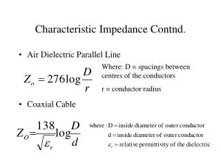
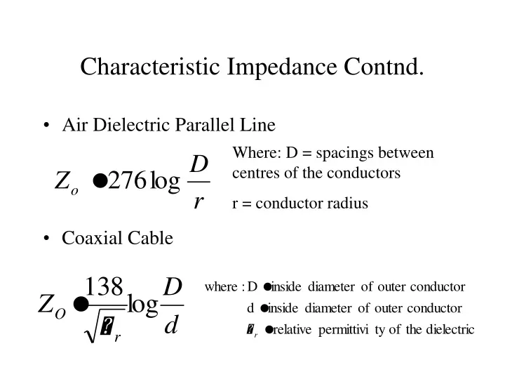
Characteristic Impedance Contnd. • Air Dielectric Parallel Line • Coaxial Cable Where: D = spacings between centres of the conductors r = conductor radius
Velocity Factor • The speed at which an energy is propagated along a transmission line is always less than the speed of light. • Almost entirely dependant upon the dielectric constant • Propagation velocity of signal can vary from 66% (coax with polyethylene dielectric) to 95%(air).
Response of Line • CONDITIONS • Step Impulses • Assume lossless line and infinite length with Zo equal to characteristic impedance of the line • Discuss: -Reflections along a line of finite length that is: a.) Open at point of termination (end of line) b.) Shorted at point of termination c.) Matched load at point of termination
Open Circuited Line • Switch is closed and followed by a surge down line. • How much of the source voltage appears across the source? (V/2) • What is the state of voltage and current at the end of the line? • For what time frame do the initial conditions exist? (2T) • What is the relative direction of incident and reflected current?(opposite)
Short Circuit Line • What is the state of voltage at the source prior to 2T? (V/2) • What is the state of voltage and current when the surge reaches the load? (V=0 and I depends on system characteristics) • What is the direction of incident and reflected current? (same)
Pulse Input To Transmission Line • With a matched line the load absorbs energy and there is no reflection • Open circuit has positive reflections • Short Circuit has negative reflections • REFLECTION COEFFICIENT(Gamma) - Open circuit line > gamma = 1 - Matched line > gamma = 0 - Short circuit line > gamma = -1
Traveling Waves Along A Line • Assume a matched line and a sinusoidal signal source. • Traveling wave • After initial conditions a steady state situation exists. • Signal will appear the same as the source at any point on the line except for time delay. • Time delay causes a phase shift ( one period = 360 degrees)
Standing Waves • Assume a transmission line with an open termination, a reasonably long line and a sinusoidal source • After initial reflection the instantaneous values of incident and reflected voltage add algebraically to give a total voltage • Resultant amplitude will vary greatly due to constructive and destructive interference between incident and reflected waves
Standing Waves contnd. • Reminder: A sine wave applied to a matched line develops an identical sine wave except for phase. • If the line is unmatched there will be a reflected wave. • The interaction of the two travelling waves (vr and vi) result in a standing wave. • SWR = Vmax/Vmin
Sample question • What length of RG-8/U (vf = .66) would be required to obtain a 30 degree phase shift at 100 Mhz?