Download
1 / 31
0 likes | 0 Views
To get the complete manual, please open the home page website.<br><br>https://www.aservicemanualpdf.com/

E N D
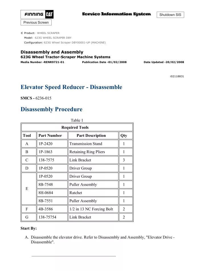
w 1/12(W) Shutdown SIS Previous Screen Product: WHEEL SCRAPER Model: 623G WHEEL SCRAPER DBY Configuration: 623G Wheel Scraper DBY00001-UP (MACHINE) Disassembly and Assembly 623G Wheel Tractor-Scraper Machine Systems Media Number -RENR9721-01 Publication Date -01/02/2008 Date Updated -20/02/2008 i02118831 Elevator Speed Reducer - Disassemble SMCS - 6236-015 Disassembly Procedure Table 1 Required Tools Tool Part Number Part Description Qty A 1P-2420 Transmission Stand 1 B 1P-1863 Retaining Ring Pliers 1 C 138-7575 Link Bracket 3 D 1P-0520 Driver Group 1 1P-0520 Driver Group 1 8B-7548 Puller Assembly 1 E 8H-0684 Ratchet 1 8B-7551 Puller Assembly 1 F 4B-3586 1/2 in 13 NC Forcing Bolt 2 G 138-75754 Link Bracket 2 Start By: A. Disassemble the elevator drive. Refer to Disassembly and Assembly, "Elevator Drive - Disassemble". https://127.0.0.1/sisweb/sisweb/techdoc/techdoc_print_page.jsp?returnurl=/sisweb/sisw... 2021/4/14
w 2/12(W) Illustration 1 g00496940 1. Attach the elevator speed reducer to Tooling (A), as shown. Place an alignment mark on the speed reducer for assembly purposes. Illustration 2 g01079336 2. Use Tooling (B) to remove retaining ring (1) from flywheel housing (2). Remove bolts (3) from flywheel housing (2) . Illustration 3 g01079337 https://127.0.0.1/sisweb/sisweb/techdoc/techdoc_print_page.jsp?returnurl=/sisweb/sisw... 2021/4/14
w 3/12(W) 3. Attach Tooling (G) and a suitable lifting device onto flywheel housing (2). Use Tooling (F) to loosen flywheel housing (2) from end plate (4). Remove flywheel housing (2) from end plate (4). The weight of flywheel housing (2) is approximately 32 kg (71 lb). Illustration 4 g01079658 4. Use Tooling (D) and a suitable press to remove roller bearing (5) (not shown) and lip seal (6) (not shown) from flywheel housing (2) . Illustration 5 g00800103 5. Attach Tooling (C) and a suitable lifting device onto flywheel (7). Remove flywheel (7) from end plate (4). The weight of flywheel (7) is approximately 12 kg (26 lb). https://127.0.0.1/sisweb/sisweb/techdoc/techdoc_print_page.jsp?returnurl=/sisweb/sisw... 2021/4/14
w 4/12(W) Illustration 6 g01079338 6. Remove retaining ring (8) and thrust disc (9) from hub (10) . Illustration 7 g00800112 7. Use Tooling (E) to remove bearing inner race (11) from hub (10). Repeat the procedure for the other side of hub (10) . Illustration 8 g01079339 https://127.0.0.1/sisweb/sisweb/techdoc/techdoc_print_page.jsp?returnurl=/sisweb/sisw... 2021/4/14
w 5/12(W) 8. Drive pin (13) into gear (12). Remove gear (12) from hub (10). Remove pin (13) from gear (12). Bend the locking tabs away from bolts (14). Remove bolts (14) and the locking tabs from flywheel (7). Remove hub (10) from flywheel (7) . Illustration 9 g00848811 9. Attach Tooling (C) and a suitable lifting device onto end plate (4). Remove end plate (4) from the ring gear. The weight of end plate (4) is approximately 19 kg (42 lb). Illustration 10 g01079340 10. Remove O-ring seal (17) from end plate (4). Use Tooling (D) and a suitable press to remove roller bearing (15) (not shown) and lip seal (16) (not shown) from end plate (4) . https://127.0.0.1/sisweb/sisweb/techdoc/techdoc_print_page.jsp?returnurl=/sisweb/sisw... 2021/4/14
https://www.aservicemanualpdf.com/ My Dear Friend! Thank you very much for visiting. Full manual if required, please enter the following URL into your browser. https://www.aservicemanualpdf.com/
w 6/12(W) Illustration 11 g00848814 11. Attach Tooling (C) and a suitable lifting device onto carrier assembly (18). Remove carrier assembly (18) from the ring gear. The weight of carrier assembly (18) is approximately 30 kg (66 lb). Illustration 12 g01079341 12. Drive spring pin (20) into shaft (19). Remove shaft (19) from carrier assembly (18). Remove spring pin (20) from shaft (19). Remove gear (21) from carrier assembly (18). Repeat the procedure for the other two gears. https://127.0.0.1/sisweb/sisweb/techdoc/techdoc_print_page.jsp?returnurl=/sisweb/sisw... 2021/4/14
w 7/12(W) Illustration 13 g01079342 13. Remove washers (23) and bearing (22) from gear (21). Repeat the procedure for the other two gears. Illustration 14 g01079343 14. Remove retaining ring (24) and sun gear (25) from the carrier assembly. Illustration 15 g00848818 15. Attach Tooling (C) and a suitable lifting device onto carrier assembly (26). Remove carrier assembly (26) from the ring gear. The weight of carrier assembly (26) is approximately 62 kg (137 lb). https://127.0.0.1/sisweb/sisweb/techdoc/techdoc_print_page.jsp?returnurl=/sisweb/sisw... 2021/4/14
w 8/12(W) Illustration 16 g00800168 16. Drive spring pin (27) into shaft (28). Remove shaft (28) and gear (29) from the carrier assembly. Remove spring pin (27) from shaft (28). Repeat the procedure for the other two gears. Illustration 17 g01079347 17. Remove washers (32), bearings (30), and spacer (31) from gear (29). Repeat the procedure for the other two gears. https://127.0.0.1/sisweb/sisweb/techdoc/techdoc_print_page.jsp?returnurl=/sisweb/sisw... 2021/4/14
w 9/12(W) Illustration 18 g01079350 18. Remove retaining ring (33), thrust washer (34), and sun gear (35) from the carrier assembly. Illustration 19 g01079352 19. Attach Tooling (C) and a suitable lifting device onto ring gear (36). Remove bolts (37) from ring gear (36). Remove ring gear (36) from housing (38). The weight of ring gear (36) is approximately 65 kg (143 lb). Illustration 20 g01079353 20. Remove spring pins (39) that lock bolts (40) into retainer plate (41). Remove bolts (40), retainer plate (41), and the shims from the housing. https://127.0.0.1/sisweb/sisweb/techdoc/techdoc_print_page.jsp?returnurl=/sisweb/sisw... 2021/4/14
w 10/12(W) Illustration 21 g01087791 21. Attach Tooling (G) and a suitable lifting device onto housing (38). Remove housing (38) from plate (42) . Illustration 22 g00800186 22. Turn over housing (38). Remove Duo-Cone seal (43) from housing (38). Use Tooling (D) and a suitable press to remove coupling gear (44) from housing (38) . Illustration 23 g00800188 https://127.0.0.1/sisweb/sisweb/techdoc/techdoc_print_page.jsp?returnurl=/sisweb/sisw... 2021/4/14
w 11/12(W) 23. Remove bearing cone (45) from coupling gear (44). Use a hammer and punch through Holes (X) in order to remove the bearing from the coupling gear. Illustration 24 g00800190 24. Remove bolts (46) from plate (47). Remove plate (47) from the housing. Illustration 25 g00800191 25. Use Tooling (D) and a suitable press to remove bearing cone (48) (not shown) and bearing cup (49) (not shown) from housing (38) . https://127.0.0.1/sisweb/sisweb/techdoc/techdoc_print_page.jsp?returnurl=/sisweb/sisw... 2021/4/14
w 12/12(W) Illustration 26 g00800194 26. Remove Duo-Cone seal (50) from plate (42). Remove spacer (51) from plate (42) . Copyright 1993 - 2021 Caterpillar Inc. Wed Apr 14 22:32:31 UTC+0800 2021 All Rights Reserved. Private Network For SIS Licensees. https://127.0.0.1/sisweb/sisweb/techdoc/techdoc_print_page.jsp?returnurl=/sisweb/sisw... 2021/4/14
w 1/12(W) Shutdown SIS Previous Screen Product: WHEEL SCRAPER Model: 623G WHEEL SCRAPER DBY Configuration: 623G Wheel Scraper DBY00001-UP (MACHINE) Disassembly and Assembly 623G Wheel Tractor-Scraper Machine Systems Media Number -RENR9721-01 Publication Date -01/02/2008 Date Updated -20/02/2008 i02118833 Elevator Speed Reducer - Assemble SMCS - 6236-016 Assembly Procedure Table 1 Required Tools Tool Part Number Part Description Qty A 1P-2420 Transmission Stand 1 B 1P-1863 Retaining Ring Pliers 1 C 138-7575 Link Bracket 3 D 1P-0520 Driver Group 1 G 138-7574 Link Bracket 2 NOTICE Keep all parts clean from contaminants. Contamination of the hydraulic system with foreign material will reduce the service life of the hydraulic system components. To prevent contaminants from entering the hydraulic system, always plug or cap the lines, fittings, or hoses as they are disconnected. Cover any disassembled components and clean them properly before assembly. https://127.0.0.1/sisweb/sisweb/techdoc/techdoc_print_page.jsp?returnurl=/sisweb/sisw... 2021/4/14
w 2/12(W) Clean the hydraulic system properly after any major component exchange or especially after a component failure, to remove any contamination. 1. Clean all parts and inspect all parts. If any parts are worn or damaged, use new parts for replacement. Illustration 1 g00800270 2. Make sure that the plate is securely placed on Tooling (A). Install spacer (51) to plate (42). Install Duo-Cone seal (50) to plate (42) . Illustration 2 g00800271 3. Lower the temperature of bearing cup (49). Install bearing cup (49) into housing (38) . https://127.0.0.1/sisweb/sisweb/techdoc/techdoc_print_page.jsp?returnurl=/sisweb/sisw... 2021/4/14
w 3/12(W) Illustration 3 g00800269 4. Position plate (47). Install bolts (46) into plate (47). Tighten bolts (46) to a torque of 55 ± 10 N·m (41 ± 7 lb ft). Illustration 4 g00800272 5. Raise the temperature of bearing cone (45). Install bearing cone (45) onto coupling gear (44) . Illustration 5 g01079903 https://127.0.0.1/sisweb/sisweb/techdoc/techdoc_print_page.jsp?returnurl=/sisweb/sisw... 2021/4/14
w 4/12(W) 6. Attach Tooling (G) and a suitable lifting device onto housing (38). Install housing (38) onto coupling gear (44) . Illustration 6 g00800274 7. Raise the temperature of bearing cone (48) (not shown). Install bearing cone (48) (not shown) into coupling gear (44) (not shown). Install Duo-Cone seal (43) . Illustration 7 g01087791 8. Attach Tooling (G) and a suitable lifting device onto housing (38). Install housing (38) onto plate (42) . https://127.0.0.1/sisweb/sisweb/techdoc/techdoc_print_page.jsp?returnurl=/sisweb/sisw... 2021/4/14
w 5/12(W) Illustration 8 g01079353 Note: Do not use an impact wrench to install bolts (40) . 9. Place three pieces of plastigage on the retainer plate for assembly purposes. Install retainer plate (41), the plastigage, and bolts (40) onto the housing. Tighten bolts (40) to a torque of 150 ± 20 N·m (111 ± 15 lb ft). Remove retainer plate (41), the plastigage, and bolts (40) from the housing. Note: Place the thinner shims between the thicker shims during installation. 10. Find the average measurement of the plastigage. Select the correct amount of shims that is equal to the measurement of the plastigage minus 0.03 ± 0.08 mm (0.0012 ± 0.0031 inch). Install retainer plate (41), the shims, and bolts (40). Tighten bolts (40) to a torque of 150 ± 20 N·m (111 ± 15 lb ft). If necessary, additionally tighten bolts (40) until spring pins (39) can be installed into retainer plate (41) . Illustration 9 g01079352 11. Attach Tooling (B) and a suitable lifting device onto ring gear (36). Install ring gear (36) onto housing (38). The weight of ring gear (36) is approximately 65 kg (143 lb). Install bolts (37) . https://127.0.0.1/sisweb/sisweb/techdoc/techdoc_print_page.jsp?returnurl=/sisweb/sisw... 2021/4/14
w 6/12(W) Illustration 10 g01079350 12. Install sun gear (35), thrust washer (34), and retaining ring (33) to the carrier assembly. Illustration 11 g01079347 13. Install spacer (31), bearings (30), and washers (32) to gear (29). Repeat the procedure for the other two gears. Illustration 12 g00800263 https://127.0.0.1/sisweb/sisweb/techdoc/techdoc_print_page.jsp?returnurl=/sisweb/sisw... 2021/4/14
w 7/12(W) 14. Install gear (29) and shaft (28) into the carrier assembly. Align the holes in shaft (28) with the hole in the carrier. Install spring pin (27) into shaft (28). Repeat the procedure for the other two gears. Illustration 13 g00848818 15. Attach Tooling (C) and a suitable lifting device onto carrier assembly (26). Install carrier assembly (26) into the ring gear. The weight of carrier assembly (26) is approximately 62 kg (137 lb). Illustration 14 g01079343 16. Install sun gear (25) and retaining ring (24) into the carrier assembly. https://127.0.0.1/sisweb/sisweb/techdoc/techdoc_print_page.jsp?returnurl=/sisweb/sisw... 2021/4/14
w 8/12(W) Illustration 15 g01079342 17. Install bearing (22) and washers (23) to gear (21). Repeat the procedure for the other two gears. Illustration 16 g01079341 18. Install gear (21) and shaft (19) into carrier assembly (18). Align the holes in shaft (19) with the hole in carrier assembly (18). Install spring pin (20) into shaft (19). Repeat the procedure for the other two gears. https://127.0.0.1/sisweb/sisweb/techdoc/techdoc_print_page.jsp?returnurl=/sisweb/sisw... 2021/4/14
w 9/12(W) Illustration 17 g00848814 19. Attach Tooling (C) and a suitable lifting device onto carrier assembly (18). Install carrier assembly (18) into the ring gear. The weight of carrier assembly (18) is approximately 30 kg (66 lb). Illustration 18 g01079340 20. Use Tooling (D) and a suitable press to install roller bearing (15) (not shown) and lip seal (16) (not shown) into end plate (4). Lubricate the lip seal with the lubricant that is being sealed. Install O-ring seal (17) onto end plate (4) . Illustration 19 g00848811 21. Attach Tooling (C) and a suitable lifting device onto end plate (4). Install end plate (4) onto the ring gear. The weight of end plate (4) is approximately 19 kg (42 lb). https://127.0.0.1/sisweb/sisweb/techdoc/techdoc_print_page.jsp?returnurl=/sisweb/sisw... 2021/4/14
w 10/12(W) Illustration 20 g01079339 22. Install hub (10) onto flywheel (7). Install the locking tabs and bolts (14). Bend the locking tabs toward bolts (14) in order to secure bolts (14). Install gear (12) onto hub (10). Align the hole in gear (12) with the hole in hub (10). Install spring pin (13) into gear (12) and hub (10) . Illustration 21 g00800283 23. Raise the temperature of inner race (11) before installation. Install inner race (11) to hub (10). Repeat the procedure for the other side. Install thrust disc (9) and retaining ring (8) to hub (10) . https://127.0.0.1/sisweb/sisweb/techdoc/techdoc_print_page.jsp?returnurl=/sisweb/sisw... 2021/4/14
w 11/12(W) Illustration 22 g00800103 24. Attach Tooling (C) and a suitable lifting device onto flywheel (7). Install flywheel (7) onto end plate (4). The weight of flywheel (7) is approximately 12 kg (26 lb). Illustration 23 g01079847 25. Use Tooling (D) and a suitable press to install roller bearing (5) (not shown) and lip seal (6) (not shown) into housing (2). Lubricate the lip seal with the lubricant that is being sealed. Illustration 24 g01079848 https://127.0.0.1/sisweb/sisweb/techdoc/techdoc_print_page.jsp?returnurl=/sisweb/sisw... 2021/4/14
w 12/12(W) 26. Attach Tooling (G) and a suitable lifting device onto flywheel housing (2). Install flywheel housing (2) onto end plate (4). The weight of flywheel housing (2) is approximately 32 kg (71 lb). Illustration 25 g01079336 27. Install bolts (3) into flywheel housing (2). Use Tooling (B) to install retaining ring (1) . End By: Assemble the elevator drive. Refer to Disassembly and Assembly, "Elevator Drive - Assemble". Copyright 1993 - 2021 Caterpillar Inc. Wed Apr 14 22:33:27 UTC+0800 2021 All Rights Reserved. Private Network For SIS Licensees. https://127.0.0.1/sisweb/sisweb/techdoc/techdoc_print_page.jsp?returnurl=/sisweb/sisw... 2021/4/14
Please write to us. Our email: aservicemanualpdf@yahoo.com Please go to the homepage to get the full manual, or other brand PDF manuals. Home Site: aservicemanualpdf.com
GET MORE OTHER MANUALS https://www.aservicemanualpdf.com/ Thank you very much for your reading. Please Click Here. Then Get COMPLETE MANUAL. NO WAITING NOTE: If there is no response to click on the link above, please download the PDF document first and then click on it. GET MORE OTHER MANUALS https://www.aservicemanualpdf.com/
w 1/4(W) Shutdown SIS Previous Screen Product: WHEEL SCRAPER Model: 623G WHEEL SCRAPER DBY Configuration: 623G Wheel Scraper DBY00001-UP (MACHINE) Disassembly and Assembly 623G Wheel Tractor-Scraper Machine Systems Media Number -RENR9721-01 Publication Date -01/02/2008 Date Updated -20/02/2008 i02118834 Elevator Drive - Assemble SMCS - 6234-016; 6235-016; 6236-012 Installation Procedure Table 1 Required Tools Tool Part Number Part Description Qty A 138-7576 Link Bracket 2 C 1P-0510 Driver Gp 1 D 5P-0960 Molybdenum Grease Illustration 1 g00506857 1. Install lip seal (16) onto shaft assembly (5). Pack bearing cone (15) with Tooling (D) before assembly. Install bearing cone (15) and spacer (14) onto shaft assembly (5) . https://127.0.0.1/sisweb/sisweb/techdoc/techdoc_print_page.jsp?returnurl=/sisweb/sisw... 2021/4/14
w 2/4(W) Illustration 2 g00506856 2. Install retaining ring (13) into housing (11) . Illustration 3 g00506855 3. Pack bearing cone (12) with Tooling (D) before assembly. Install bearing cone (12) into housing (11) . https://127.0.0.1/sisweb/sisweb/techdoc/techdoc_print_page.jsp?returnurl=/sisweb/sisw... 2021/4/14
w 3/4(W) Illustration 4 g01079931 4. Use Tooling (C) and a suitable press to install bearing cone (12) (not shown) and housing (11) onto shaft assembly (5) . Illustration 5 g00506852 5. Install washer (10) and bolt (9) onto shaft assembly (5) . Illustration 6 g01079235 6. Install the gasket and cover (8) onto shaft assembly (5). Install bolts (7) . https://127.0.0.1/sisweb/sisweb/techdoc/techdoc_print_page.jsp?returnurl=/sisweb/sisw... 2021/4/14
https://www.aservicemanualpdf.com/ My Dear Friend! Thank you very much for visiting. Full manual if required, please enter the following URL into your browser. https://www.aservicemanualpdf.com/