Download
1 / 21
220 likes | 475 Views
Waves at Boundaries. Flow from the transmitter (Tx) to the receiver (Rx) A signal is created electrically and flows through a transmission line The signal goes to an antenna, where it is radiated into the air When the signal reaches the air-water interface, it is refracted

E N D
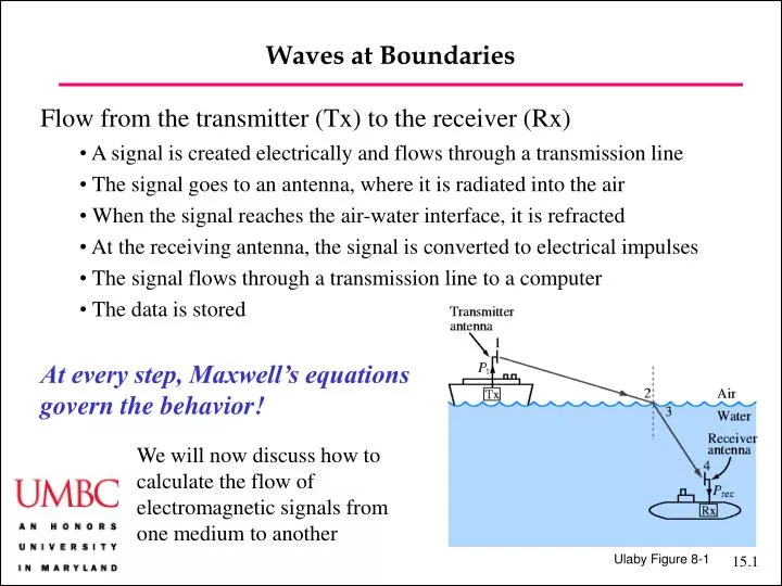
Waves at Boundaries • Flow from the transmitter (Tx) to the receiver (Rx) • A signal is created electrically and flows through a transmission line • The signal goes to an antenna, where it is radiated into the air • When the signal reaches the air-water interface, it is refracted • At the receiving antenna, the signal is converted to electrical impulses • The signal flows through a transmission line to a computer • The data is stored • At every step, Maxwell’s equations • govern the behavior! We will now discuss how tocalculate the flow of electromagnetic signals fromone medium to another Ulaby Figure 8-1
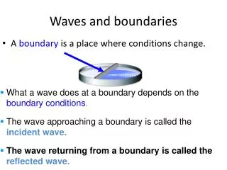
Waves at Boundaries • Reflection and transmission • When a wave encounters a boundary between two media,part is transmitted and part is reflected • The media are characterized by different values for h1and h2. • This behavior is analogous to what isobserved at the boundary of twotransmission lines with twodifferent impedances • We will use rays to represent the flowof electromagnetic waves. Rays are arrows that point in the direction of the k-vectors and are orthogonal to the wavefronts • Wavefront = points where the field has constant phase Ulaby Figure 8-2
Waves at Boundaries • Normal and oblique incidence • A signal can strike a boundary surface at any angle • Normal incidence = the k-vector of the signal is orthogonal to the surface • Oblique incidence = the k-vector of the signal is not orthogonal to the surface • Normal incidence is simpler to describe and very important; so we treat it first Ulaby Figure 8-3
Normal Incidence • Lossless Media • We consider two media that are lossless with the boundary at z = 0 — the media are characterized by e1, m1 and e2, m2 • An x-polarized plane wave is normally incident • We then have • Incident wave: • Reflected wave: • Transmitted wave:
Normal Incidence • Lossless Media • Incident wave: • Reflected wave: • Transmitted wave: • The incident and transmitted wave propagate in the +z-direction • The reflected wave propagates in the –z-direction • Mathematical Consequences:
Normal Incidence • Lossless Media • There are no free charges or currents The E and H fields are all continuous across the boundary • Fields in Medium 1 (z < 0): • Fields in Medium 2 (z > 0): • Matching the fields at z = 0:
Normal Incidence • Lossless Media • Reflected and transmitted amplitudes • G = reflection coefficient • t = transmission coefficient; t = 1 + G • Another expression: Using • we have Ulaby 2001
Normal Incidence • Standing Wave Ratio • Reflected and transmitted amplitudes • G = reflection coefficient • t = transmission coefficient; t = 1 + G • This result generalizes to the case where h1 and h2 are complex. • When h1 is real, we have Just as in the case of transmission lines, we can define a standing-wave ratio and determine pointswhere the amplitude oscillations are maxima and minima Ulaby 2001
Normal Incidence Plane Wave Transmission Line Transmission Line Analogies
Normal Incidence • Power Flow in Lossless Media • We have • Note that cross-terms cancel! As a consequence:
Normal Incidence • Power Flow in Lossless Media • We also have • Using the relation • we conclude And energy is conserved! As it should be
Normal Incidence Radar Radome Design: Ulaby Example 8-1 Question: A 10 GHz aircraft radar uses a narrow-beam scanning antenna mounted on a gimbal. Over the narrow extent of the antenna beam, we can assume that the radome shape is planar. If the radome material is a lossless dielectric with mr = 1 and er = 9, choose the thickness d such that the radome appears transparent to the radar beam. Mechanical integrity requires d > 2.3 cm. Answer: This is an impedance-matching problem — analogous to impedance-matchingproblems that we saw in the study of transmission lines. Ulaby Figure 8-5
Normal Incidence Radar Radome Design: Ulaby Example 8-1 Answer (continued): There will be noreflection if the input impedance matches theair impedance h0. For a single polarization,we may define the input impedance as since medium 2corresponds to the transmission line. Itfollows that with So, we have (where n is an integer) Ulaby Figure 8-6
Normal Incidence Radar Radome Design: Ulaby Example 8-1 Answer (continued): So, we choose The value n = 5 is the minimum that allowsus to obey the condition for structuralintegrity, and we conclude d = 2.5 cm. Ulaby Figure 8-6
Normal Incidence • Lossy Media • We may generalize our results to lossy media by using the transformation • We thus obtain in medium 1:and in medium 2:with
Normal Incidence Normal Incidence on a Metal Surface: Ulaby Example 8-3 Question: A 1 GHz x-polarized TEM wave traveling in the +z-direction and is incident in air upon a metal surface coincident with the x-y plane at z = 0. The incident electric field amplitude is 12 mV/m, and we have for copper . Obtain expressions for the instantaneousfields in the air medium. Assume that the metal surface is more than five times the skin depth in thickness. Answer: In medium 1 (air), a = 0, andAt f = 1 GHz, copper is an excellent conductor because
Normal Incidence Normal Incidence on a Metal Surface: Ulaby Example 8-3 Answer (continued): We obtain for the intrinsic impedance This is very small in magnitude compared to h0, so the copper surface acts like a short circuit, and we have so that we find
Normal Incidence Normal Incidence on a Metal Surface: Ulaby Example 8-3 Answer (continued): Returning to the time domainThe standing-wave patterns are shown to the left. Note that the E-field is shorted out, while the H-field remains large. As a consequence, it is harder to shieldmagnetic fields than electric fields Ulaby Figure 8-8
Applications—Paul Chapter 5 • Shielding • Shielded enclosures are used to either (a) prevent a signal from outside the enclosure from interfering with equipment inside or (b) vice versa. Using the same geometry as in the radome problem (and Ulaby’s notation), we find analogously • which in the limit of a good conductor with highreflections and many (> 5) times the width of theskin depth becomes Paul Figure 5.19
Applications—Paul Chapter 5 • Shielding • We define the shielding effectiveness of the enclosure: • There is a reflection term and an absorption term. Below are results for 20 mil sheets of copper and steel. Reflection dominates below 2 MHz for copper and below 20 kHz for steel. Paul Figure 5.21
Applications—Paul Chapter 5 • Microwave Health Hazards • Microwave devices work at about 2 GHz. The human body has Regulatory agencies set safe levels at10 mW/cm2, corresponding to |E0| = 275 V/m. Damage comes from skin heating. How much power is absorbed at the “safe” level? • We begin by noting that s /we = 0.27. The human body is a quasi-conductor at this frequency. We have t = 0.244(0.99 + j0.11) andg2 = 39.6 + j 298, so that a2 = 39.6 and d = 2.5 cm. We find • Slightly over half the power is reflected.