Download
1 / 11
110 likes | 157 Views
Explore fixed frequency oscillators, control power in clock circuits, and system poles for oscillation stability. Understand design principles like Barkhausen Criteria and Root Locus. Learn about oscillator types, such as Hartley and Colpitts circuits, for efficient signal generation. Study amplifier gain calculations and feedback networks to optimize performance. Discover how to prevent oscillation amplitude growth and ensure stable operation in electronic systems.

E N D
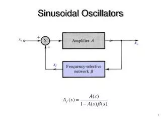
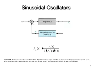
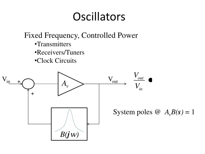
Fixed Frequency, Controlled Power • Transmitters • Receivers/Tuners • Clock Circuits Oscillators Vin Vout + Av + System poles @ AvB(s) = 1 B(jw)
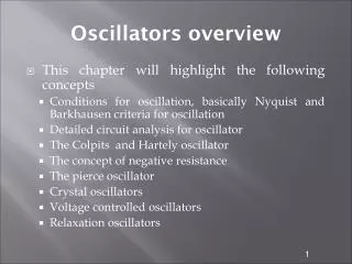
Barkhausen Criteria System poles @ AvB(s) = 1 w0 Pole in RHP: Oscillation amplitude grows until amplifier starts to clip, then Av’ < Av. Root locus for Av’ < Av
Oscillator Design Vin Vout + Av + B(jw) Common Base: rin = re Av = Rc’/re Common Emitter: rin = (b+1)re Av = -Rc’/re Frequency Selective Feedback Network LC Network Quartz Crystal
Amplifier Gain • Av = + Rc’/re • re = 26 mV/IE (from DC Analysis) • Rc’ : Parallel Combination of • Transformed Load: RL’ = RL/av2 • Parasitic Loading (finite Q): Rcoil = QuXT • Feedback Network: Re’ = . . . . . • Collector Dynamic (AC) Resistance: rc~ 20 k • Any other resistances in Collector Circuit
Hartley Oscillator(common base, autotransformer feedback) C E
Hartley Oscillator VCC + - VCC C IC= b IB R1 LT , Qu b , rc IB B n1 CT DC Equivalent IE= (b+1) IB R1 n2 n3 RL E R2 re R3 R2 R4 BP R3 BP AC Equivalent R4 E C ie n2 + ve - rc re R3 n1 B
B1vc R4 ve = B1B2vc E C + vc - ie n2 + ve - rc RP re R3 n1 B Ideal B=B1B2 ve = Bvc E C + vc - ie + ve - rc RP re R3 B
ve = Bvc E + vc - C ie + ve - rc RP re B ve = Bvc Note: any additional resistance placed across the tank circuit must be included as an additional parallel contribution. B B E C + vc - ie + ve - re B
Barkhausen: is AVB > 1 ? Book Example : f = 1 Mhz IC~ IE= 1 ma n1= 10, n2= 100, n3= 5 (subscripts changed) LT = 53 uH, Qu = 50, XT = 333 W RL= 50 W R3 = 1 k W R4= 0 W (therefore, B2 = 1) rc = 50 k W AV VCC LT , Qu b , rc B n1 CT R1 n2 n3 RL re R2 R4 BP R3 BP
Maximum Power Considerations The maximum 0-pk collector AC voltage is: The maximum power to the load is: VCC was not given for this problem, but we can determine a minimum value required to prevent saturation at max power by recalling that . . .