Download
1 / 27
310 likes | 732 Views
Digital to Analog. Many carrier facilities are analog Many transmission media are also analog (microwave, radio) We can carry digital values over analog signals We must ‘ encode ’ the digital data over the digital signal This is what is done with modems. Modem. digital. Analog.

E N D
Digital to Analog • Many carrier facilities are analog • Many transmission media are also analog (microwave, radio) • We can carry digital values over analog signals • We must ‘encode’ the digital data over the digital signal • This is what is done with modems Modem digital Analog Modem = Modulation/Demodulation
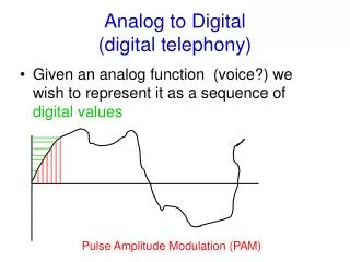
Encoding Digital Data • We can encode data (bits) onto regular analog sine waves or example. • Consider a sine wave y = sin(x)
Analog Signal • Beyond a basic period, the wave repeats itself • The time for one non repeating part of the signal is called the period • The number of times the wave repeats itself during a unit of time is called the frequency • Units of measure are usually the number of cycles (repetitions) per second • Cycles per second are called Hertz • frequency = 1 / period
Analog Signal • Each signal has an amplitude or level
Analog Signal • Each Signal has a frequency
Analog Signal • Signal can also have a phase shift
Encoding bits with Analog Signals • Encoding using amplitude change
Bandwidth • Bandwidth is a measure of channel or circuit capacity • Bandwidth is in part determined by the number of times a signal changes value or frequency • Frequency is measured in Hertz • Both digital and Analog signals have frequency • Every circuit or channel has a frequency limit • Due to Hardware • Due to limitation of media • Artificially introduced • Data bandwidth is the capacity of a circuit to carry data and is usually measure in bits per second or bps
Bandwidth • Consider a regular home phone line • This is an analog circuit • The frequency of that signal is limited by the phone company • The circuit carries sound in frequencies between 300 Hz and 3300 Hz • For separation the phone company allocates 4000 Hz for each phone line or phone call
Baud Rate • Speed of a circuit is measured in baud • Baud • The number of times a circuit can change value • If each change represents 1 bit then • Baud Rate = Bit Rate • In all our previous examples • Baud Rate = Bit Rate
Suppose we could create a number of levels, for example, say we had 8 voltages levels we could use 111 110 101 100 011 010 001 000
011 000 100 111 000 001 110 010 Suppose we receive 111 110 100 011 010 001 000 000
Maximum Data Rateof a Channel ** Harry Nyquist (1924) showed Max data rate (bps) = 2 * H * log2(V) Where H = frequency of channel in Hertz V = number of distinct signal levels Example – Voice grade line - 4000 Hz (3000 usable) If we use 2 signal levels MDR = 2 * 3000 * log2(2) = 6,000 bps
Nyquist’s Result • This result assumes a noiseless channel • We never have a ‘clean’ channel • Noise • Distortion • Attenuation • Interference • Circuits have a rating called Signal to Noise Ratio – measured in decibels S = measure of the power of the signal N = measure of the power of the noise
Limitations of Hardware • Regardless of transmission type, signals degrade over distances • Level or power of signal may degrade, called attenuation • Shape of signal may degrade, especially digital signals. This is called distortion. • Interference from external sources (NEXT) • So, how fast can we send bits? How short can we make a ‘bit time’? • Maximum bit rate is therefore limited by the media and the sensitivity of hardware to be able to accurately recreate transmitted bits
Attenuation Signals on any media are subject loss of signal strength over distances Let P0 = initial power of a signal Pm = measured power at some distance of m unit Power ratio = Common measure is decibels ***
Maximum Data Ratefor ‘noisy’ channel Signal to Noise ratio = S/N Decibel = 10 * log10(S/N) Claude Shannon (1948) Maximum data rate of a channel ** = H * log2( 1 + S/N) H = frequency of channel Example – voice grade line Signal to noise is approximately 30 DB Mdr = 3000 * log2( 1 + 1000) = 3000 * log2( 1001 ) = 30,000 (approximately) Regardless of the number of signals used
Modems • Encode digital values over analog circuits • To encode data, modems use combinations of • Amplitude Shift Keying (ASK) • Frequency Shift Keying (FSK) • Phase Shift Keying (PSK) • Typically, a carrier frequency is provided and various SHIFT KEYING is applied • For half duplex we could have only one carrier • For full duplex, we need two carriers, one for each direction
Modems • There have been many modem standards over time • Early modems used a form of frequency shifting – Ex 300 bps full duplex modem • Originating modem • Sine wave at 1070 Hz for a 0 bit • Sine wave at 1270 Hz for a 1 bit • Answering modem • Sine wave at 2025 Hz for a 0 bit • Sine wave at 2225 Hz for a 1 bit
Modems • Later modems used combinations of shift keying by combining PSK and ASK • Some common 9600 bps modems used • 12 phase shifts at 1 amplitude • 4 phase shift at a second amplitude • Combination of 16 different states • Called Quadrature Amplitude Modulation (QAM) • Baud rate was 2400 cycles per second • Each of the 16 states represented 4 bits
Modems Standard Baud Bit Modulation rate rate Technique V.21 300 300 FSK V.22 600 600/1200 PSK V.22bis 600 1200/2400 QAM V.23 1200 1200 FSK V.32 2400 4800/9600 QAM/TCM V.34 2400 28,800 V.90 2400 56,000 V.92 2400 56,000
Modems • To improve performance, compression and error correction standards developed • Two compression standards in in vogue • V.42bis • MNP 5 • Two error correction standards • V.42 • MNP 4