Download
1 / 58
620 likes | 960 Views
IP & SoC Verification. Contents. IP Verification Cycle-level Transaction Level Testbench build-up Hardware debugging An example (iPROVE) SoC Verification Design Flow Multi-level, multi-lingual verification Multiple-FPGA set-up Debugging An example (iSAVE). IP verification.

E N D
Contents • IP Verification • Cycle-level • Transaction Level • Testbench build-up • Hardware debugging • An example (iPROVE) • SoC Verification • Design Flow • Multi-level, multi-lingual verification • Multiple-FPGA set-up • Debugging • An example (iSAVE)
IP verification • Important issues • IP reuse • Testbench reuse • Debuggability • Testbench issues • Various testbench support • HLL: C/C++ • HDL: Verilog and VHDL • De facto standards: SCE-MI, SystemC, OpenVera and so on • Various levels of testbench • Transaction-level: control by command level, e.g., read/write • Cycle-level: control over pin-by-pin • Abstract-bus-level: standard on-chip networks
Cycle-level verification • Cycle-level verification DUT (HDL) Testbench (C/HDL) Device Driver PCI Controller DUT Buffer/ Pin Signal Generator Testbench PCI Channel S/W simulation part FPGA part
Cycle-level verification • SW: Testbench • Modeled with HDL or C language • Generate stimulus at every clock cycle • Check the result of DUT at every clock cycle • HW: DUT • Mapped on FPGA • Stimulus are transferred through a system bus, e.g., PCI. • All signals are assigned to DUT concurrently after they are transferred from the SW test bench. • Operating speed • Faster than SW simulation due to the acceleration of HDL or C model of DUT in FPGA. • Determined by the interface requirement (number and bandwidth of signals to be transferred), and bandwidth of the interface (PCI)
Transaction-level verification • Transaction-level verification DUT Testbench Device Driver Main Memory PCI Controller Transactor DUT Testbench DMA Channel S/W simulation part FPGA part
Transaction-level verification • SW: Testbench • Modelled with C language • Generate stimulus and check the result of DUT • Only information enough to form the transaction is transferred to DUT. • i.e., command, address and data • HW: DUT and transactor • Mapped on FPGA • Transactor knows how to interpret the transaction and thence generates all signals necessary for DUT. • Operating speed • HW and SW parts are operated independently. • Faster than cycle-level verification as well as SW simulation.
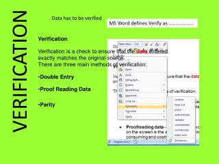
Testbench automation • Overview • SCE-MI • VERA • Test Builder
SCE-API (MI) • Standard Co-Emulation API (Modeling Interface) • SW part implemented as C or C++, with recommendation on HW implementation • Based on IKOS’ multi-channel co-modeling technology: TIP (Transaction Interface Portal) • SCE-API Consortium • Founded June 2000 • Aptix, CoWare, IKOS, Mentor, STMicroelectronics, Synopsys, TransEDA • SCE-API version 1.0 modeling interface • SCE-MI v1.0 released through Open SystemC Initiative (http://www.systemc.org), April 2001 • Accellera’s Interface Technical Committee • Merged into ITC, Oct. 2001 • SCE-DI (Debug Interface) & SCE-CI (Control Interface) on progress
Vera • Vera • Functional verification language for testbench description • Language specification can be obtained from OpenVera site (http://www.opera-vera.com) • Vera Language • Object-oriented language • Includes HDL features • Waiting clock event • Bit data type, bit operation (extraction, concatenation) • Data expectation (‘do something when the expectation is hit’) • 0,100 bus.ack == 1; // ack must be 1 in at least 100 cycles • Vera Verification Environment • Commercial product from Synopsys • Vera source codes are compiled and runs with HDL simulator in which DUT is simulated. • Additional features • Automatic stimulus generation, Coverage analysis
Vera .vr –Vera Source Vera Compiler .vrh –Vera Header HDL Simulator .vro –Vera Object Vera Shell Vera PLI DUT .vrl –Vera List Supplied by User Automatically generated by Vera compiler
TestBuilder • Transaction-Based Verification Functional verification in higher level of abstraction Engineer develops tests from a system level perspective • Advantages • Enhance reusability of each component in the testbenches • Improve debugging and overage analysis Transaction Level Signal Level TVM (Transactor) Design Tests TVM: Transaction Verification Model
TestBuilder • How TestBuilder Operates Transaction Level Signal Level Tests TVM DUV While(){ Tx.send_packet(..); Mem.expect_write(..); .. } Tx.send_packet(..){ header = “hd”; address = 0xff0011; data = 0xff0011; } C/C++/TestBuilder Implementable using TestBuilder/HDL HDL C library (PLI/FLI) HDL Simulation
Specman • Functional Testbench Automation Tool by Verisity (http://www.verisity.com) • Its concept is similar to Vera, but starts earlier and more widely used. • Describe user specification with e language Interface Spec & Test Plan by e Legacy codein C/VHDL/Verilog Specman Elite AutomaticTestbenchGeneration Data & TemporalChecking Coverage Analysis DUT
Debugging feature • Built-In Logic Analyzer (BILA) • DUT boundary – ports • DUT internal – internal nodes iPROVE PCI Board PC
Hardware debugging schemes • Low speed scheme • Operating speed: < 10MHz • There is no dedicated storage element in the device. • All debugging information is transferred to main memory or large storage device at every cycle. • Readback scheme of Xilinx device is a typical example. • Usually, the scheme needs only a small number of IO pins. • JTAG interface: 4 pins (TCK, TDI, TMS, TDO) • 8-bit parallel interface (CLK, INIT, CS, RW, D[7:0])
Hardware debugging scheme • High speed scheme • Operating speed: < 100MHz • There is several dedicated elements which can be internal memories or external memories. • All debugging information is stored in the dedicated elements. • Typical example • Xilinx: ChipScope • Altera: SignalTap-II
iPROVE is a small scale design verification tool by enabling C/C++, HDL and de facto standards interfacing API’s. API Proprietary C/C++ API Proprietary Verilog API SCE-API/MI What is iPROVE Testbench and/or rest blocks in C, HDL and/or SystemC IP in HDL/EDIF PCI bus
iPROVE tool positioning Running Speed Real Silicon 100MHz 10MHz Rapid Prototype 1MHz HW Emulator iPROVE 100KHz 10KHz HW Accelerator 1KHz 100Hz SW Simulator 10Hz Investment
iPROVE typical usage: IP verification DUT Automatically generated module PC iPROVE Test Testbech IP PCI DPP Signal information Signals Interactive IO Cycle-level verification IP verification without prototyping Transactors DUT Test Transactions Signals Transaction-based verification DUT BFM Test DUT bus Abstract-bus-based verification
iPROVE typical usage: DPP PC iPROVE Multi-media board Large size data PCI DPP
User design Verilog, VHDL User testbench C/C++, Verilog, VHDL OS Windows 2000 or XP Linux De facto standards SCE-MI/API SystemC OpenVera TestBuilder API C/C++ Visual C Borland C GNU GCC under Cygwin Verilog iPROVE structure
iPROVE design flow synthesis P&R compilation Mapping by running testbench execution Debugging with BILA
Cycle-level with Verilog (1/3) • A simple ALU example
Cycle-level with Verilog (2/3) • Step 1: Start with EDIF of the ALU – need synthesizer • Step 2: make FPGA mapping data • Step 3: modify testbench by inserting PLI’s for iPROVE • Step 4: run the ALU with iPROVE and HDL simulator Testbench runs at host computer DUT goes to iPROVE
Testbench example(Cycle-level) *alu-proxy is image of ALU mapped on FPGA `define CARD_ID 0 module alu_top(); // inputs and outputs … always #5 clk = ~clk; `ifdef iPROVE alu_proxy(…) `else alu(…) `endif alu_sim(.resetb(resetb), .clk(clk), .cmd(cmd), .src1(op1), .src2(op2), .cin(carry), .result(result), .cf(cf), .vf(vf), .nf(nf), .zf(zf)); // other thestbench codes initial begin $dumpfile("alu.vcd"); $dumpvars(); `ifdef iPROVE $iProveOpenCard(`CARD_ID); $iProveInitCard(`CARD_ID, “ALU.tcf"); $iProveLoadModuleInfoFile(`CARD_ID, "ALU.mit"); $iProveCycLoadSignalInfoFile("alu", “ALU.pin"); `endif clk = 1'b0; resetb = 1'b1; repeat (2) @ (posedge clk); resetb = 1'b0; repeat (2) @ (posedge clk); resetb = 1'b1; // other testbench codes `ifdef iPROVE $iProveCloseCard(`CARD_ID); `endif $stop; end endmodule Automatically generated by iPROVE software $iProveCycSignalWrite(modhl_alu, sighdl_reset,reset); $iProveCycSignalWrite(modhl_alu, sighdl_cmd,cmd); … $iProveCycClockAdvanceByModule(modhl_alu, sighdl_clk); $iProveCycSignalRead(modhl_alu, sighdl_cf, cf); $iProveCycSignalRead(modhl_alu, sighdl_vf, vf); … $iProve…; system task for iProve defined as PLI routine
Transaction-level with C (1/3) • A simple SSRAM example
Transaction-level with C (2/3) • Step 1: Start with EDIF of the SSRAM – need synthesizer • Step 2: make FPGA mapping data • Step 3: modify testbench by inserting PLI’s for iPROVE • Step 4: run the SSRAM with iPROVE and HDL simulator DUT & transactor goes to iPROVE Testbench runs at host computer
Testbench example(Transaction-level) #include “iprove.h” int main(int argc, char** argv) { // other codes iProveOpenCard(card_id); iProveInitCard(card_id, tcf); iProveLoadModuleInfoFile(card_id, mit); iProveGetModuleHandle(instance_name, &module_handle); iProveAllocReadBuffer(module_handle, sbm_size); iProveAllocWriteBuffer(module_handle, sbm_size); #ifdef BILA iProveBILAConfig(card_id, trg); iProveBILATrigOn(card_id); #endif iProveStart(card_id); TestBench(); #ifdef BILA iProveBILAUpload(card_id, dmp); bila_info.cid = card_id; bila_info.dump_filename = dmp; bila_info.signallist_filename = lst; WithCheck(iProveDump2Vcd(&bila_info, 1, vcd); #endif iProveStop(card_id); iProveCloseCard(card_id); return 0; } void TestBench(void) { // other codes iProveCmdWrite(module_handle, &cmd, 1); iProveDataWrite(module_handle, pbuf, num, &tmp); // other codes iProveCmdWrite(module_handle, &cmd, 1); iProveDataRead(module_handle, pbuf, num, &tmp); // other codes }
Performance comparisons IDCT: 59K gates FPACC0: 56K gates FPACC1: 104K gates FPACC2: 208K gates
iPROVE performance • iPROVE provides outstanding speed-up over x2000. • Example • FPACC2 (Floating-point number calculation IP) • Gate count: 208,479 • Logic usage: 99% of XCV1000E x2053 x47 x69 x1 iPROVE iPROVE iPROVE ModelSim with ModelSim with Cycle- Level C-API with Transaction -Level C-API
Easy to use and fast setup time to emulation No or minor source modification The same testbench for simulation and emulation Various verification mode Cycle, transaction and abstract bus modes Powerful debugging BILA (Built-in Logic Analyzer) as a real hardware logic analyzer High-performance interface to S/W side High-speed DMA feature High to low level languages such as C/C++, Verilog and VHDL Open interface system API layer provides easy-to-interface mechanism to de facto standards Scalability Multiple iPROVE cards as well as various gate count options iPROVE-Summary
SoC Verification • Key technologies in SoC Verification • Early/Consistent Verification Environment • Progressive Refinement • Multi-level, Multi-lingual Verification
Make it faster Ideal Verification Solution Make it cheaper ASIC Verification Methods Running Speed Real Silicon 100MHz 10MHz Rapid Prototype 1MHz HW Emulator 100KHz 10KHz HW Accelerator 1KHz 100Hz SW Simulator 10Hz Investment
What’s the point in SoC Verification? • Mixture of SW and HW • Make it easier to cooperate with Processor Model such as ISS or BFM • Mixture of pre-verified, not-verified components • Make it easier to utilize legacy IPs already verified • Mixture of different language, different abstraction level • Provide common interface structure between SoC components
System Spec. HW IP HW-SW System Design Co-Design SW IP HW-SW Co- HW/SW Verification Partitioning Functional Software Verification Verification HW SW Development Development SW refinement HW refinement (RTOS (UT->T->RTL) mapping) Gate-Level Verification Gate Final code Canonical SoC design flow • Emulator • In-system emulator • HW-SW co-debugging
Tools for HW-SW Co-Verification • HW-SW co-simulation • ISS • RTOS simulator System Spec. HW IP System Design SW IP HW-SW Co- HW/SW HW/SW Verification Partitioning Functional Software Verification Verification HW SW Development Development SW refinement HW refinement (RTOS (UT->T->RTL) mapping) • High-level synthesis • Testbench automation • IP accelerator
Tools for System-level • System-level design (Performance analysis tools) • Hot-spot analyzer • High-level cycle count estimation • High-level power analysis • High-level chip area estimation • On-chip-bus traffic estimation System Spec. HW IP HW-SW System Design Co-Design SW IP HW/SW Partitioning
Verification Environment • Early test-bench setup • Accurate and fast test-bench setup in early design stage greatly reduces verification time and efforts • Consistent test-bench utilization • Once the test-bench is built up, it must be consistently reused in the following design steps • In-system test bench • The test bench must be switchable between SW simulation and in-system verification to cover all corner cases.
In-System Verification In-System Gate Level Verification design synthesis manufacture Integration test silicon spec. RTL gate board functional verification formal verification test pattern In-System Behavioral Level Verification
Flexible Verification Environment C TestBench HDL Test Bench In-SystemTest Bench ConventionalVerificationEnvironment C Model HDL Design Gate LevelDesign In-SystemTest Bench HDL Test Bench C TestBench HDL Test Bench In-SystemTest Bench FlexibleVerificationEnvironment C Model Gate LevelDesign C Model HDL Design Gate LevelDesign
uP Core SRAM FLASH D-Cache USB MPEG FIFO SRAM Logic Progressive refinement • With the advent of design reuse methodology for System-On-a-Chip designs, a mixture of C, HDL, EDIF netlist and IP core blocks is required to be verified together as one system. • For a large design, it is necessary to verify each design blocks/modules one after another until whole design is verified. • IP has to be prepared in various abstraction levels in order to support progressive refinement process. A typical SoC chip EDIF RTL BCA TF Incremental/progressive refinement UTF
Multi-Level & Multi-Lingual level of abstraction Multiple Programmable Cores (20%) Algorithm Functional Memory (20~50%) other IPs (>20%) UT Custom contents (15~20%) Behavioral BCA RTL CA gate TA EDIF (gate-level netlist) HDL (Veilog VHDL) SystemC (HW) C/C++ (HW) C/C++ (SW) UT: untimed, BCA: bus cycle accurate CA: cycle accurate, TA: timing accurate RTL: register transfer level
Supporting Multi-Language • Simulation Vehicle • HDL Simulator • User C process ( C/C++/SystemC model for HW or SW ) • ISS for embedded processor core • Test description language (Vera, TestBuilder) • Emulation Vehicle • FPGA containing one or more IP’s (enables gate-level IP verification) • FPGA interfacing with target system (enables in-system verification) • Communication channel between vehicles • IPC (inter-process communication) for designs simulated in multiple processes • Dedicated device driver for designs mapped in FPGAs
Supporting Multi-Level • Bridging abstraction gap • Using transactor • Using cycle-level transactor Read Channel Write Channel Transaction-LevelC/HDL Model Transactor CycleAccurateHDL/EDIF Model Read Channel Write Channel Cycle-LevelTransactor CycleAccurateC/HDL Model CycleAccurateAPI CycleAccurateModel
Multi-Level & Multi-Lingual C sessions HDL sessions Design in Verilog Design in VHDL Design in C Design in SystemC Transactor Transactor Inter-Lingual Communication TIE EDIF sessions I/F protocol I/F protocol Transactor Transactor Design in EDIF Design in EDIF Target board
iSAVE-MP & MPEG2/4 iSAVE-MP main iSAVE-MP TIM GUI windows Decoded image MPEG Board
SoC model with ARM CCM Debugger ARM CCM Memory model IP models IP in HDL AMBA model Address Decoder Bus wrapper ILC(Inter-lingual Communication)
FPGA1 FPGA2 Bus Split Logic Using Multiple FPGA’s • Using multiple FPGAs • Partitioning into multiple FPGAs • Bus split Host Processor ARM ISS Memory Model Transactor Transactor IP0 IP1 IP3 IP2