Download
1 / 25
270 likes | 484 Views
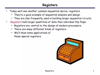
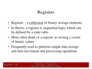
Assembly Variables: Registers. Unlike HLL like C or Java, assembly cannot use variables Why not? Keep Hardware Simple Assembly Operands are registers Limited number of special locations built directly into the hardware Operations can only be performed on these!

E N D
Assembly Variables: Registers • Unlike HLL like C or Java, assembly cannot use variables • Why not? Keep Hardware Simple • Assembly Operands are registers • Limited number of special locations built directly into the hardware • Operations can only be performed on these! • Benefit: Since registers are directly in hardware, they are very fast
ARM Integer Arithmetic Replace xy with bb (bottom/bottom bits), bt (bottom/top bits), tb (top/bottom bits), tt(top/top bits)
ARM Load/Store Instructions Replace xy with bb (bottom/bottom bits), bt (bottom/top bits), tb (top/bottom bits), tt(top/top bits)
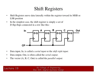
ARM Load/Store Instructions • The ARM is a Load/Store Architecture: • Does not support memory to memory data processing operations. • Must move data values into registers before using them. • This might sound inefficient, but in practice isn’t: • Load data values from memory into registers. • Process data in registers using a number of data processing instructions which are not slowed down by memory access. • Store results from registers out to memory.
ARM Load/Store Instructions • ARM has three sets of instructions which interact with main memory. These are: • Single register data transfer (LDR/STR) • Block data transfer (LDM/STM) • Single Data Swap (SWP) • The basic load and store instructions are: • Load and Store Word or Byte or Halfword • LDR / STR / LDRB / STRB / LDRH / STRH • Syntax: • <LDR|STR>{<cond>}{<size>} Rd, <address>
Single register data transfer LDR STR Word LDRB STRB Byte LDRH STRH Halfword LDRSB Signed byte load LDRSH Signed halfword load • Memory system must support all access sizes • Syntax: • LDR{<cond>}{<size>} Rd, <address> • STR{<cond>}{<size>} Rd, <address> e.g. LDREQB
Single register data transfer LDR STR Word LDRB STRB Byte LDRH STRH Halfword LDRSB Signed byte load LDRSH Signed halfword load • Memory system must support all access sizes • Syntax: • LDR{<cond>}{<size>} Rd, <address> • STR{<cond>}{<size>} Rd, <address> e.g. LDREQB
Data Transfer: Memory to Register • To transfer a word of data, we need to specify two things: • Register: r0-r15 • Memory address: more difficult • Think of memory as a single one-dimensional array, so we can address it simply by supplying a pointer to a memory address. • Other times, we want to be able to offset from this pointer. Remember: Load FROM memory
Base Register Addressing Modes • There are many ways in ARM to specify the address; these are called addressing modes. • A register which contains a pointer to memory • Example: [r0] • specifies the memory address pointed to by the value in r0
Data Transfer: Memory to Register • Load Instruction Syntax: 1 2, [3] • where 1) operation name 2) register that will receive value 3) register containing pointer to memory • ARM Instruction Name: • LDR (meaning Load Register, so 32 bits (one word) are loaded at a time)
Data Transfer: Memory to Register Data Flow • Example: LDR r0,[r1] This instruction will take the pointer in r1, and then load the value from the memory pointed to by this calculated sum into register r0 • Notes: • r1 is called the base register
Data Transfer: Register to Memory • Also want to store value from a register into memory • Store instruction syntax is identical to Load instruction syntax • MIPS Instruction Name: STR (meaning Store Register, so 32 bits or one word are loaded at a time) • Example: STR r0,[r1] This instruction will take the pointer in r1and store the value from register r0 into the memory address pointed to by the calculated sum Remember: Store INTO Memory Data Flow
Memory r0 SourceRegisterfor STR 0x5 r1 r2 DestinationRegisterfor LDR BaseRegister 0x200 0x5 0x200 0x5 Base Register Addressing Mode • The memory location to be accessed is held in a base register • STR r0, [r1] ; Store contents of r0 to location pointed to ; by contents of r1. • LDR r2, [r1] ; Load r2 with contents of memory location ; pointed to by contents of r1.
Immediate Offset Addressing Mode • To specify a memory address to copy from, specify two things: • A register which contains a pointer to memory • A numerical offset (in bytes) • The desired memory address is the sum of these two values. • Example: [r0,#8] • specifies the memory address pointed to by the value in r0, plus 8 bytes
Immediate Offset Addressing Mode • Load Instruction Syntax: opcoderd, [rn, #imm] • where opcode - operation name rd - register that will receive value rn - register containing pointer to memory imm - numerical offset in bytes
Immediate Offset Addressing Mode • Example: LDR r0, [r1,#12] This instruction will take the pointer in r1, add 12 bytes to it, and then load the value from the memory pointed to by this calculated sum into register r0 • Example: STR r0, [r1,#-8] This instruction will take the pointer in r0, subtract 8 bytes from it, and then store the value from register r0 into the memory address pointed to by the calculated sum • Notes: • r1 is called the base register • #constant is called the offset • offset is generally used in accessing elements of array or structure: base reg points to beginning of array or structure
r0 SourceRegisterfor STR Memory 0x5 Offset 12 0x5 0x20c r1 BaseRegister 0x200 0x200 Immediate Offset Addressing Mode • Example: STR r0, [r1,#12] • To store to location 0x1f4 instead use: STR r0, [r1,#-12] • To auto-increment base pointer to 0x20c use: STR r0, [r1, #12]! (called immediate pre-indexed addressing mode) • If r2 contains 3, access 0x20c by multiplying this by 4: • STR r0, [r1, r2, LSL #2] (called scaled register offset addressing mode)
Memory r0 r1 Offset SourceRegisterfor STR UpdatedBaseRegister 0x5 0x20c 12 0x20c 0x5 0x200 r1 OriginalBaseRegister 0x200 Post-indexed Addressing Mode • Example: STR r0, [r1], #12 • To auto-increment the base register to location 0x1f4 instead use: • STR r0, [r1], #-12 • If r2 contains 3, auto-increment base register to 0x20c by multiplying this by 4: • STR r0, [r1], r2, LSL #2
Memory Offset element 3 12 Pointer to start of array 2 8 1 4 r0 0 0 Using Addressing Modes Efficiently • Imagine an array, the first element of which is pointed to by the contents of r0. • If we want to access a particular element,then we can use pre-indexed addressing: • r1 is element we want. • LDR r2, [r0, r1, LSL #2] • If we want to step through everyelement of the array, for instanceto produce sum of elements in thearray, then we can use post-indexed addressing within a loop: • r1 is address of current element (initially equal to r0). • LDR r2, [r1], #4 Use a further register to store the address of final element,so that the loop can be correctly terminated.
Pointers vs. Values • Key Concept: A register can hold any 32-bit value. That value can be a (signed) int, an unsigned int, a pointer (memory address), and so on • If you write ADD r2,r1,r0 then r0 and r1 must contain values • If you write LDR r2,[r0] then [r0] must contain a pointer • Don’t mix these up!
Called the “address” of a word Addressing: Byte vs. word • Every word in memory has an address, similar to an index in an array • Early computers numbered words like C numbers elements of an array: • Memory[0], Memory[1], Memory[2], … • Computers needed to access 8-bit (byte) as well as words (4 bytes/word) • Today machines address memory as bytes, hence 32-bit (4 byte) word addresses differ by 4 • Memory[0], Memory[4], Memory[8], …
Notes about Memory • Pitfall: Forgetting that sequential word addresses in machines with byte addressing do not differ by 1. • Many an assembly language programmer has toiled over errors made by assuming that the address of the next word can be found by incrementing the address in a register by 1 instead of by the word size in bytes. • So remember that for both LDR and STR, the sum of the base address and the offset must be a multiple of 4 (to be word aligned)
0 1 2 3 Aligned Not Aligned More Notes about Memory: Alignment • ARM typically requires that all words start at byte addresses that are multiples of 4 bytes Last hex digit of address is: 0, 4, 8, or Chex 1, 5, 9, or Dhex 2, 6, A, or Ehex 3, 7, B, or Fhex • Called Alignment: objects must fall on address that is multiple of their size.
Role of Registers vs. Memory • What if more variables than registers? • Compiler tries to keep most frequently used variables in registers • Less common in memory: spilling • Why not keep all variables in memory? • Smaller is faster:registers are faster than memory • Registers more versatile: • ARM arithmetic instructions can read 2, operate on them, and write 1 per instruction • ARM data transfer only read or write 1 operand per instruction, and no operation