Download
1 / 18
180 likes | 302 Views
shutter for release to accelerator. drive laser: 81.25 MHz, sync’d to master RF l = 1064 nm ~7 ps pulses ~10 watts average (~120 nJ/pulse). chopper wheel: ~100Hz, ~120 m s opening. variable beam size optics. solenoid shutter: 1, 2, 5, 10, 20 Hz. pulse stacker: output ~28 ps pulses.

E N D
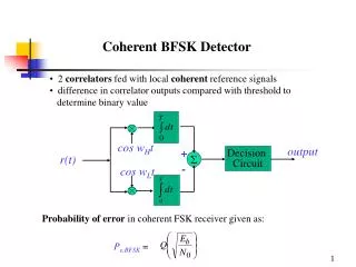
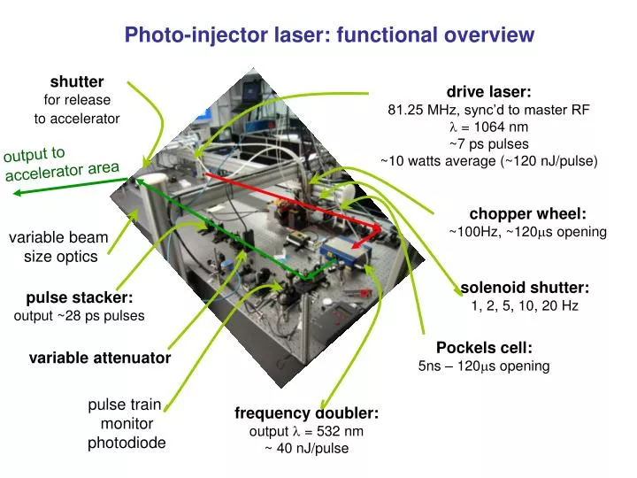
shutterfor release to accelerator drive laser: 81.25 MHz, sync’d to master RFl = 1064 nm ~7 ps pulses ~10 watts average (~120 nJ/pulse) chopper wheel: ~100Hz, ~120ms opening variable beam size optics solenoid shutter: 1, 2, 5, 10, 20 Hz pulse stacker: output ~28 ps pulses Pockels cell: 5ns – 120ms opening variable attenuator pulse train monitorphotodiode frequency doubler: output l = 532 nm ~ 40 nJ/pulse Photo-injector laser: functional overview output to accelerator area
Photo-injector laser: functional overview shutterfor release to accelerator drive laser: 81.25 MHz, sync’d to master RFl = 1064 nm ~7 ps pulses ~10 watts average (~120 nJ/pulse) output to accelerator area chopper wheel: ~100Hz, ~120ms opening variable beam size optics solenoid shutter: 1, 2, 5, 10, 20 Hz pulse stacker: output ~28 ps pulses Pockels cell: 5ns – 120ms opening variable attenuator pulse train monitorphotodiode monitored/changedin normal operation frequency doubler: output l = 532 nm ~ 40 nJ/pulse changed occasionally
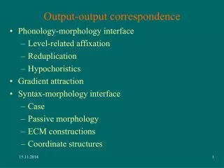
photo-injector lasers transport mirrors on translation stages light box cathode virtual cathode Laser room lasersource beam on virtual cathode exit from laser room [mm] cathode [mm]
photo-injector lasers transport Movable mirrors for changing beam position on cathode “HTM”horizontal “VTM”vertical
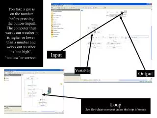
CW “unchopped”pulse train chopped, 532nm, train (macrobunch, before attentuator) master 81.25MHz delivered to laser room
Laser timing signals Chopper detect chopper open signal used for RF triggering (also with ~23 ms advance) shutter open general trigger signal (for BPM’s, cameras, etc) max pretrigger ~270ms pockels cellopen/close
Laser system controls... drive laser shutter open/closed (laser operators key required) shutter to accelerator open/closed (general control panel operation) laser macro-bunch length & external trigger signals
Chan A: Pockels cell open (~270ms) Chan B: macro-pulse width (~5ns- 100ms) Chans C, Dused by BPMs control can be released for manual “local” operation in laser room “internal” triggering used for equip testing when laser not operational
opens laser position control.. left-right defined fromelectron frame NOT looking back at cathode KNOWN “bug”: if power lost to motor control, the control-system zero position will change. (restarts at zero on control system, but motors actually at position as before power cycle)
Viewing the (real) cathode ERLPcon2 desktop “Pylon viewer” New (more reliable) camera, BUT, not yet tested with laser beam on cathode.... Sensitivity to be determined on startup camera synchronised to laser macro bunch train
Viewing the (real) cathode... Looking at scattered light from cathode, though side port on light-box • not enough light with short macro bunch trains • observed profile dependent on scattering flatness of cathode • position is reliable (not dependent on survey, etc) as viewed with old camera.... new colour camera to be used this commissioning period
Viewing the virtual cathode • sensitive enough for monitoring laser with “few-bunch” train lengths • beam position accuracy depenent on survey (can cross-check with real cathode at long bunch trains) from underneath light-box cross-hairfor alignment reference variable attenuator (for camera sensitivity/protection) “virtual cathode” icon on ERLPcon1 desktop no camera control screen shots for now....(will add later) camera synchronised to laser macro bunch train
Laser-RF synchronisation spacing set by round trip