Download
1 / 33
330 likes | 473 Views
Computer-controlled trigger system of the DIRAC experiment. A.Kulikov on behalf of the DIRAC collaboration. DIRAC ( DImeson Relativistic Atomic Complex) at PS CERN. The purpose of the experiment is study of exotic atom-like bound states of p and K mesons:

E N D
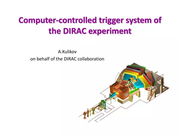
Computer-controlled trigger system of the DIRAC experiment A.Kulikov on behalf of the DIRAC collaboration
DIRAC (DImeson Relativistic Atomic Complex) at PS CERN. The purpose of the experiment is study of exotic atom-like bound states of p and K mesons: p+p-, p+K-, p-K+, [K+K-]. Such “atoms” are produced (with a very small probability) in interactions of the proton beam with a nuclear target . Measurement of the lifetime of these atoms (of the order of 10-15 s) allows to obtain the values of pp, pK and KK scattering lengths. These quantities are calculated within the Chiral Perturbation Theory with a high precision but are not measured experimentally with a good enough accuracy. Production rate of the atoms is several orders of magnitude less than of free pppairs, therefore one needs a selective trigger. Varna, NEC'2013 A.Kulikov
Method of the atom detection Atoms consisting ofpp(or pK, KK) mesons are very “fragile” and disintegrate into a pair of free particles while passing through even thin layer of matter of about 100 mm. A specific feature of the pairs from the atom disintegration is very small relative momentum of the two particles, Q < 3 MeV/c (while their laboratory momenta are within the 2 GeV/c < P < 7 GeV/c interval). Q < 3 MeV/c Smallness of the relative momentum is a distinctive feature of such “atomic” pairs which is usedat the trigger level in order to select useful events from a huge flux of hadron pairs. Varna, NEC'2013 A.Kulikov
While planning and building the trigger system, the following baseline principles were taken into account: • the system should provide as much as possible background suppression Varna, NEC'2013 A.Kulikov
While planning and building the trigger system, the following baseline principles were taken into account: • the system should provide as much as possible background suppression • selection criteria should not cut useful events Varna, NEC'2013 A.Kulikov
While planning and building the trigger system, the following baseline principles were taken into account: • the system should provide as much as possible background suppression • selection criteria should not cut useful events • parallel running of different triggers is required Varna, NEC'2013 A.Kulikov
While planning and building the trigger system, the following baseline principles were taken into account: • the system should provide as much as possible background suppression • selection criteria should not cut useful events • parallel running of different triggers is required • on-line and off-line monitoring of the trigger performance. • This is very important because improper trigger functioning may lead to • losses of useful events or to systematic biases in the collected data Varna, NEC'2013 A.Kulikov
While planning and building the trigger system, the following baseline principles were taken into account: • the system should provide as much as possible background suppression • selection criteria should not cut useful events • parallel running of different triggers is required • on-line and off-line monitoring of the trigger performance. This is • very important because improper trigger functioning may lead to • losses of useful events or to systematic biases in the collected data • by requirements of the experiment, the trigger conditions should • alternate periodically. Therefore, it is strongly desirable that • changes of trigger could be easily done by any experimentalist • on shift, without presence of the experts in electronics. Varna, NEC'2013 A.Kulikov
DIRAC setup DC- drift chambers , VH – vertical hodoscopes, HH – horizontal hodoscopes, Ch – nitrogen Cherenkov , PSh - preshowerdetectors, Mu - muon detectors Upgraded DIRAC setup 24 GeV/c MDC - microdrift gas chambers, SFD - scintillating fiber detector, IH– ionization hodoscope. Modified parts Varna, NEC'2013 A.Kulikov
1-st level trigger (T1) Combining detector signals in different ways in coincidence/anticoincidence schemes, so called “trigger primitives” in both arms were constructed: p1 = VH1*HH1*Ch1 e1= VH1*HH1*Ch1 p2= VH2*HH2*Ch2 e1= VH2*HH2*Ch2 K1 = p1*VH1cut*ChF1 K2= p2*VH2cut*ChF2 …………. The 1-st level trigger is built mainly of commercially available modules of CAEN and LeCroy. Further coincidence of “primitives” from both arms produced first level trigger of different kinds: p+p- e+e- p+K- p-K+ p-p (L–trigger) 3p (K-trigger) 4e etc. Varna, NEC'2013 A.Kulikov
Methods of low relative momentum events selection at the trigger level 1. Coplanarity selection: small Dy in the downstream part Fast coplanarity processor evaluates data from the downstream scintillation hodoscopes with horizontally oriented scintillators. The event is accepted if a difference between the hit slab numbers Dn ≤ 2. This retains only events with a low Qycomponent. 1 N1 1 N2 Y 16 16 Dn =│N1-N2│ dedicated CAMAC module Varna, NEC'2013 A.Kulikov
2. Small Dx in the upstream part (T2) Selection using scintillating fiber detector: two hits with Dx≤ 9 mm. dedicated electronics Varna, NEC'2013 A.Kulikov
2. Small Dx in the upstream part (T2) Selection using scintillating fiber detector: two hits with Dx≤ 9 mm. Selection using the upstream scintillation hodoscope(6 mm strip width): either hits in adjacent strips are required or double ionization in a single strip. This retains only events with a low Qx component. dedicated electronics or commercial CAMAC modules Varna, NEC'2013 A.Kulikov
3. Limitation of the QLcomponent (T3): dedicated FPGA based processor analyzes the hit patterns in two downstream and the upstream scintillation hodoscopes. dedicated CAMAC module Rejection power – 2.0 Efficiency – 97% QL≤ 30 MeV/c Varna, NEC'2013 A.Kulikov
4. Neural network trigger dedicated electronics Magnet Target Neural network was trained to select particle pairs with low relative momenta: Qx ≤ 3 MeV/c, Qy ≤ 3 MeV/c, QL ≤ 30 MeV/c to electronics of the neural network trigger Rejection power – 2.0 Efficiency – 99% in the low momentum region. Varna, NEC'2013 A.Kulikov
5. Drift chamber processor (T4) reconstructs straight tracks in the X-projection and analyzes them with respect to relative momentum. dedicated CAMAC modules selection: Qx ≤ 3 MeV/c, QL≤ 30 MeV/c Rejection power – 5.0 Efficiency > 99% in the low momentum region. Varna, NEC'2013 A.Kulikov
Results of trigger selection by low relative momentum Distribution on relative momentum Q with different levels of trigger enabled Varna, NEC'2013 A.Kulikov
Results of trigger selection by low relative momentum Distribution on relative momentum Q with different levels of trigger enabled Efficiency as a function of Q Same with expanded low Q region Varna, NEC'2013 A.Kulikov
Trigger formation and operation Using the modules of combinatory logics, dedicated coplanarity processor and drift chamber processor (and some others at an early stage of the experiment) a number of triggers was constructed: Ap+p- AK+p- AK-p+ p+p- e+e- 2e+2e- L→ p-p K→ 3p main physics triggers triggers for calibration and other physics which can run in parallel, with individual prescaling factors. Varna, NEC'2013 A.Kulikov
Trigger formation and operation Formation of the 1-st level trigger Two-level trigger scheme Start ADC, TDC etc. T1 Clear ‾ T4 Readout DC data + Varna, NEC'2013 A.Kulikov
Trigger formation and operation The state of all electronics is given by the trigger file which describes the structure of the trigger logic and sets parameters of the front-end electronics. Host computer Varna, NEC'2013 A.Kulikov
Trigger formation and operation The state of all electronics is given by the trigger file which describes the structure of the trigger logic and sets parameters of the front-end electronics. When the measurement cycle starts, the host computer forms the load file from the trigger file and the electronic configuration file (containing physical addresses of the modules). Host computer Varna, NEC'2013 A.Kulikov
Trigger formation and operation The state of all electronics is given by the trigger file which describes the structure of the trigger logic and sets parameters of the front-end electronics. When the measurement cycle starts, the host computer forms the load file from the trigger file and the electronic configuration file (containing physical addresses of the modules). The VME processor addresses the created load file and, using the program library of CAMAC commands, provides loading of the parameters into all controlled electronic modules. Host computer Varna, NEC'2013 A.Kulikov
Trigger formation and operation Trigger file Hodoscopes Cherenkov counters command files …. …. Trigger types Processor operation processor activation, loading of selection criteria trigger types enabled, prescaling factors thresholds, signal widths, delays, channel masking commands Trigger file consists of command files, each of them is a list of commands to be sent to the modules. A command file includes a group of commands which refer to a definite detector or are united by some other common purpose. As a rule, in order to change conditions of the data taking, it is needed to change parameters of only part of the electronic modules, therefore it is sufficient to modify only the corresponding command file(s). Varna, NEC'2013 A.Kulikov
Trigger formation and operation For any configuration of the trigger logic and front-end electronics to be used in a beam time, the corresponding trigger file is prepared. The needed file is selected from the list of files which opens on the screen at the start of data taking. Trigger files, command files and configuration file are text files whatis easy-to-use. Varna, NEC'2013 A.Kulikov
Monitoring of the trigger system performance Primary test is fulfilled at the loading of the trigger file: 1) comparison of the really detected modules with the content of the configuration file; 2) readout of the loaded parameters and comparison of the read data with the set data; 3) test of the drift chamber processor. This is automatically done at the beginning of each measurement cycle in order to check that “good” events are not rejected by the processor. Varna, NEC'2013 A.Kulikov
Monitoring of the trigger system performance Primary test is fulfilled at the loading of the trigger file: 1) comparison of the really detected modules with the content of the configuration file; 2) readout of the loaded parameters and comparison of the read data with the set data; 3) test of the drift chamber processor. This is automatically done at the beginning of each measurement cycle in order to check that “good” events are not rejected by the processor. The results of the trigger file loading , including all set parameters, are written in an electronic logbook. This allows, if needed, to check at off-line data analysis which values of the parameters were loaded to the modules. e-logbook Varna, NEC'2013 A.Kulikov
On-line monitoring Measurement of the counting rates for each trigger type at all trigger levels in each accelerator cycle. These counts are displayed on the monitors and recorded in the data flow. Each event has an individual label of the trigger type, therefore, information on the trigger type is available not only integrally but for any separate event. Accumulation of the histograms (hundreds!) from all the detectors and from essential points of the trigger logic. They can be controlled not only visually on the screen, but also in the automatic mode when the monitoring program compares the real spectra with the reference spectra. If their difference exceeds some preset value, the program informs the experimentalist on duty. Varna, NEC'2013 A.Kulikov
Off-line trigger performance analysis Test of the trigger processors In order to test the efficiency of high level triggers the data are periodically takenwith only T1 as an active trigger, while the higher level triggers do not controlrecording of data but evaluate the events and write the marks of their positiveor negative decisions. At off-line express analysis, the relative momentum Q is calculated for each event and therefore it can be specified as “good” (if Q is small) or “bad” (if Q is large) event. Then it is checked which mark was assigned to the event by the processor – “good” or “bad” , and so the rejection powerof the processors and their efficiency are tested. Varna, NEC'2013 A.Kulikov
Off-line trigger performance analysis More labor-consuming but overall test of all trigger levels (including T1) can be fulfilled using the minimum bias trigger. In this mode triggering and recording of data is initiated by a signal from only one detector (“VH”).It is possible that the signals of other detectors could be found in the recorded event (though with a very small probability), and conditions forthe 1st level trigger could be fulfilled and, moreover, even for selection by the trigger processors. In these cases the corresponding trigger marks are issued. Off-line analysis of the recorded data allows to find the events where the conditions for generation of trigger were fulfilled and therefore the trigger marks should present. Then comparison with actually issued trigger marks allows to estimate the trigger efficiency at all levels. Varna, NEC'2013 A.Kulikov
Conclusions The DIRAC trigger apparatus is multilevel hardware system which provided data flow reduction using event selection basedon relative momentum. All operations with trigger are fulfilled via computer, without manual interference. Performance of the trigger system is permanently under control. Varna, NEC'2013 A.Kulikov
Conclusions The DIRAC trigger apparatus is multilevel hardware system which provided data flow reduction using event selection basedon relative momentum . All operations with trigger are fulfilled via computer, without manual interference. Performance of the trigger system is permanently under control. Thank you for your attention! Varna, NEC'2013 A.Kulikov
Most of electronics of the experiment is in CAMAC and VME standard. Nevertheless, some NIM modules are also used. Those NIM modules (a little) which status should change at the change of the data taking conditions, are included in electronic logic in a special way, with use of the CAMAC output register. This provides possibility to modify the function of the NIMmodule without manualoperations. output CAMAC register output CAMAC register Varna, NEC'2013 A.Kulikov