Download
1 / 13
130 likes | 355 Views
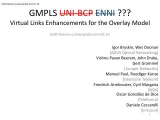
draft-beeram-ccamp-gmpls-uni-bcp-00.txt . GMPLS UNI Best Current Practices. draft-beeram-ccamp-gmpls-uni-bcp-00.txt V.Beeram, I.Bryskin, W.Doonan (ADVA Optical Networking) J.Drake, G.Grammel

E N D
draft-beeram-ccamp-gmpls-uni-bcp-00.txt GMPLS UNIBest Current Practices draft-beeram-ccamp-gmpls-uni-bcp-00.txt V.Beeram, I.Bryskin, W.Doonan (ADVA Optical Networking) J.Drake, G.Grammel (Juniper Networks) M.Paul, R. Kunze (Deutsche Telekom)
draft-beeram-ccamp-gmpls-uni-bcp-00.txt Introduction • GMPLS • Provides tools to create and manage end-to-end services in various transport technologies • GMPLS_UNI • RFC 4208 discusses how GMPLS can be applied to the overlay model. • [GMPLS_UNI_BCP] • Attempts to pool together the best current practices that are being used to apply the GMPLS Overlay model at the UNI reference point. • Based on experiences drawn from interoperating GMPLS-enabled IP routers with Optical Transport elements • Could be generalized for any client-server layer combinations
draft-beeram-ccamp-gmpls-uni-bcp-00.txt Hierarchical Network B E G J C F H A D I
draft-beeram-ccamp-gmpls-uni-bcp-00.txt Traffic Engineering • Path computation and qualification operations occur within a given layer • Topology and resource availability information required by elements of the client-layer network is distinct from that required by elements of the server-layer network • One way to setup an end-to-end client-layer path in a hybrid network is to use an ERO with a “loose hop” across the server-layer domain. • This would cause the server-layer to create the necessary segment of the client-layer topology on the fly. • Drawbacks: • necessity for operator to specify ERO with “loose” hop • potential sub-optimal usage of resources • unpredictability WRT fate-sharing of the new segment created on the fly with other links of the client-layer topology.
draft-beeram-ccamp-gmpls-uni-bcp-00.txt Augmenting client-layer topology • To enable computing paths between pairs of client-layer endpoints the client-layer topology must be augmented to indicate possible paths across the network domain which can provide transport for the client-layer connections. • Segments of the client-layer topology over the network domain should be pre-planned and made available (in terms of TE links and nodes that exist in the client-layer) to all the clients.
draft-beeram-ccamp-gmpls-uni-bcp-00.txt Augmenting client-layer topology Client TEDB = server-layer B E = client-layer G J C A F H Create “TE Link” between F and J in the client-layer by creating underlying server-layer connection D I B E Have client-layer links end-to-end, can do CSPF G J C F H A D I
draft-beeram-ccamp-gmpls-uni-bcp-00.txt Virtual TE Links • Virtual TE Link is a TE link that is advertised into the client-layer with no active server layer trail set up to support the TE link • Fundamental properties of a Virtual TE Link are: • It is advertised just like a real/regular TE link (client-layer elements see no difference between virtual and real links) • It can share server-layer resources with other virtual TE links • When a virtual TE link is signaled in the ERO of a client-layer connection, it ceases to be “Virtual” and transforms into a regular TE-link . • When this transformation takes place, the clients notice the change in the advertised available bandwidth of this TE link. • All other Virtual TE links that share server layer resources with the link in question start advertising “zero” available bandwidth.
draft-beeram-ccamp-gmpls-uni-bcp-00.txt Hierarchical Service Activation Client TEDB = server-layer B E = client-layer G J C A F H Create “Virtual TE Link” between F and J in the client-layer without actually instantiating the underlying server-layer connection D I B E Have client-layer links end-to-end, can do CSPF G J C F H A D I
draft-beeram-ccamp-gmpls-uni-bcp-00.txt Macro SRLGs • TE links that are added to the client-layer topology may not be totally independent • If diverse end-to-end client-layer connections are to be computed, fate-sharing information of the TE links needs to be accounted for. • Traditional SRLGs • Traditional SRLG represents a shared physical network resource upon which normal function of a link depends • Scalability issues exist with using physical SRLGs in multi-layer environments • SRLG IDs may collide in the client layer advertisements • Macro SRLGs • Address scalability and uniqueness of IDs • Same protocol format as that of traditional SRLGs • Assigned automatically for each TE link that is advertised into the client-layer • Each Macro SRLG represents a path segment that is traversed by 2 or more of the underlying server-layer connections.
draft-beeram-ccamp-gmpls-uni-bcp-00.txt Macro SRLGs = server-layer Client TEDB B E = client-layer G SRLG 25 J SRLG 25 C A F H • “TE Links” E-I and F-J share fate (Underlying server-layer connections traverse the same path segment – [G-H][H-I]) • Macro SRLG-ID “25” assigned to both the “TE-Links” D I B E G J C F H A D I
draft-beeram-ccamp-gmpls-uni-bcp-00.txt Switching Constraints • Optical network configurations often necessitate specification of connectivity constraints in the TE advertisements. • If constraints associated with the binding between a TE link served by the server domain and its associated access TE link are not advertised, there is a risk of an invalid path being picked. • Extensions specified in [draft-ietf-ccamp-general-constraint-encode] address this
draft-beeram-ccamp-gmpls-uni-bcp-00.txt Switching Constraints A B C D A1 B1 B3 C1 C3 D1 A2 B2 B4 C2 C4 D2 TE Links served by the server domain B3-C1 B4-C2 Access TE Links A1-B1 C3-D1 A2-B2 C4-D2 Valid Paths [A1-B1][B3-C1][C3-D1] [A2-B2][B4-C2][C4-D2] Invalid Paths [A1-B1][B4-C2][…] [A2-B2][B3-C1][…] [A1-B1][B3-C1][C4-D2] [A2][B4-C2][C3-D1] Switching Constraints B1 B3 B2 B4 C1 C3 C2 C4