Download
1 / 47
470 likes | 653 Views
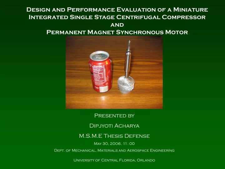
Design and Performance Evaluation of a Miniature Integrated Single Stage Centrifugal Compressor and Permanent Magnet Synchronous Motor. Presented by Dipjyoti Acharya M.S.M.E Thesis Defense May 30, 2006, 11: 00 Dept. of Mechanical, Materials and Aerospace Engineering

E N D
Design and Performance Evaluation of a Miniature Integrated Single Stage Centrifugal Compressor and Permanent Magnet Synchronous Motor Presented by Dipjyoti Acharya M.S.M.E Thesis Defense May 30, 2006, 11: 00 Dept. of Mechanical, Materials and Aerospace Engineering University of Central Florida, Orlando
Collector Impeller Inlet Guide Vane Coupler Top plate Diffuser Controller Koford Electric Motor Components of the Centrifugal Compressor Courtesy : Ray Zhou, Kevin Finney
P1, T1 P2, T2 P3, T3 P4, T4 Compressor Experimental Setup
Issues to be resolved • Resolve misalignment issues • Design of new coupler to handle high speeds • Design a new electric motor to handle the power required by compressor
Stainless steel retaining ring was slip fit • Coupler more rigid and prevented it from handling any misalignment Disc couplings style –WM Berg Coupler Problems with Rimitec Coupler • Servo-insert coupling allowed a restricted amount of misalignment • Elastic material in the middle began to plastically deform
Design of the Helical Coupler • Why use a flexible shaft coupling ? Rigid couplings would have been always used if itwere possible to perfectly align these shafts 2) Helical Flexure 3) Multiple Starts • Best for high speed application • Double Start, Ansys Analysis Heli-cal Inc. 4) Flexure Creation Process Wire EDM, Dynamically balanced while in production Martensitic stainless steel CC455 H900 per AMS 5617 5) Material
Helical Coupler Courtesy: Heli-cal Products Company Inc.
Alignment Issues and translational stages • Straight Edge • Laser Alignment Systems - Laser systems • 3) Dial indicator methods are • RIM FACE METHOD • REVERSE RIM METHOD
Reverse Rim Alignment Method SCHEMATIC DIAGRAM OF COMPRESSOR – MOTOR SYSTEM FOR REVERSE RIM ALIGNMENT METHOD · M = the offset in the plane of the movable indicator. · S = the offset in the plane of the stationary indicator. · A = the distance between the stationary and movable dial indicator plungers. · B = the distance from the movable dial indicator plunger to the movable machine’s front feet bolt center. · C= the distance between the movable machines’ front and rear feet bolt centers.
Available Drivers for Centrifugal Compressor Electric Motor Air-Turbine Turbocharger Speeds 158,000 rpm 250,000 rpm 200,000 rpm Accessories Controller TC-Control System Mist Lubricator Speed Controlling Unit Coupling Flexible Coupler Spline Shaft Spline Shaft Cost $ 2500 $ 30,000 $35,000 Required speed 108,000 rpm. Achieved Speed 90,000 rpm
Shear Stress Analysis Maximum Shear Stress Theory Power being transmitted = P = 2000 W Speed of rotation of the shaft = N = 200000 rpm Angular velocity of rotation = ω = 2* π *N/60 Torque developed = T = P/ ω = 0.095 N.m Maximum allowable shear stress = τ max Factor of Safety = F = 3 a = ASME factor for shaft design for shear = ¾ No vertical shear stress Rigidity modulus of the shaft m/l = γ = 117 GPa Angle of shaft twist because of torsion = α (maximum for the outer layer) For a τmax value of 20305 psi (for a Titanium), d = 15.846 mm Thickness of the hollow shaft = t = [D – d]/2 = 0.077 mm << 0.5 mm So, the shaft would not fail under pure shear. Also, Angle of Twist
Bending Stress The values considered for the bending stress are as follows, Elastic modulus of shaft = 116,000 MPa Poisson’s ratio for shaft = υ = 0.34 Ultimate tensile strength of the shaft = 220 MPa Elastic modulus of permanent magnet = 150,000 MPa Poisson’s ratio for permanent magnet(ν) = 0.3 Ultimate tensile strength of the permanent magnet = 82.7 MPa Bending moment due to impeller weight = M = 3.74 N-mm Shaft cross-section – Hollow Shaft Permanent magnet cross-section – Solid Shaft Density of the shaft m/l (ρshaft) = 4500 kg/m3 Density of the permanent magnet (ρmagnet) = 7500 kg/m3 Maximum bending stress (σmax) = M/Z, where Z = section modulus. σmax ,Titanium = 0.037 MPa << Ultimate tensile strength of shaft. σmax, Permanent Magnet = 0.048 MPa << Ultimate tensile strength of permanent magnet. So the shaft would not fail under pure bending.
Fracture Toughness Fracture Toughness is an issue at cryogenic temperatures. It is defined k = cs(√ π*c)α, where ‘k’ is the ‘Critical Stress Intensity’, Cs – Critical Stress, c – crack length, α – geometry factor (depends on the cross-section of the member) ‘k’ depends on the Bending Stress developed.
Centrifugal Stress Analysis • Centrifugal stress developed in shaft at 200K rpm = 728 MPa. • Centrifugal stress developed in magnet at 200K rpm = 261.2 MPa
Thermal Analysis Stress due to centrifugal force in shaft rotating at 200,000 rpm = 728 MPa Stress due to centrifugal force in magnet rotating at 200,000 rpm = 251.2 MPa Thermal stress developed in shaft due to operating at 77 K = 329 MPa The Total Stress = 1308.2 MPa < Titanium Grade Yield Strength 1420 MPa So the titanium shaft would not fail. Also, Thermal Stress developed in magnet = 130 MPa < Compressive Strength = 833 MPa. So, the magnet would not crack or crumble to powder. • Thermal stress developed in the shaft at 77 K = 329 MPa • Thermal stress developed in the magnet at 77 K = 130 MPa
Rotordynamic Analysis of Rotor Courtesy: Dr. Nagraj Arakere , UF, Gainsville
Design of the Integrated Compressor –Motor System • Elimination of the coupler • Reduction of number of bearings in the system • Usage of fewer components on the rotor to increase the stiffness
Test Accessories – Electrical Emulator, DSP and Motor Controller Low Pass Filter Power Meter Code Composer Courtesy: Liping Zheng and Limei Zhou
Test Accessories – Flow P-Transducers Mass Flow Meter
Bearing mounting, fit and pre-load Roarke’s Handbook of Stress and Strain Courtesy : Krishna
Integrated Compressor – Motor Test Set-up Motor Jacket Stator inside Gas enclosure with adjustable IGV to control tip clearance
Two Piece Rotor • Free spin test results were successful only to 42,000 rpm • Wobbling near the aluminum impeller plug by 0.008 inches • Hair crack was visible at the joint Externally Threaded Shaft Internally Threaded Impeller Fabricated Two Piece Rotor
Problems and Future Work in Test Setup • Vibrations experienced around 34000 – 37000 rpm range. • - leading to stoppage • Bearings cooling method to be determined.
Conclusion Initial Compressor-Motor Test Setup developed and tested • Helical Coupler was designed and tested • Alignment method was improved by Reverse Rim Method and Translational Stages • Components were verified with FARO Arm and re-fabricated 2 KW Permanent Magnet Synchronous Motor designed and tested • Shaft Material Selection, Stress Analysis Performed and Optimized by Rotordynamic Analysis. Bearing Selection • Fabrication, Assembly Performed and Tested • Motor-Generator set developed to determine motor performance Integrated Compressor – Motor Structure Designed and Tested -Versions of Integrated Rotor was designed and tested • Bearing Fit determined, Pre-load structure designed • Innovative procedure for alignment developed • Adjustable IGV developed for control over tip clearance