Download

1 / 9
430 likes | 3.44k Views
Exercise: Indexing of the electron diffraction patterns. Louisa Meshi. Formation of electron diffraction and HRTEM image . (hkl) plane. 1/ d hkl * 1/2. g/2. specimen. sin = = =. 1/ . 1/ . 2 . = /2d hkl. 1/ . g hkl. P hkl. Bragg’s law. O.

E N D
Exercise:Indexing of the electron diffraction patterns Louisa Meshi
(hkl) plane 1/dhkl * 1/2 g/2 specimen sin= = = 1/ 1/ 2 =/2dhkl 1/ ghkl Phkl Bragg’s law O Points of reciprocal lattice Origin of the reciprocal lattice Ewald sphere construction: Bragg’s conditions are satisfied when the Ewald sphere cuts a reciprocal lattice point specified by the indices of the reflecting plane.
specimen 1/ Ewald sphere (1/>>g) Camera Length (L) = L r r 1\ g ; rdhkl=L, L - camera constant r For diffraction in electron microscope: The single crystal electron diffraction pattern is a series of spots equivalent to a magnified view of a planar section through the reciprocal lattice normal to the incident beam.
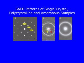
Types of electron diffraction patterns: • Ring pattern – from polysrystalline specimen. Major use: • Identification of the phases; • Analysis of texture; • Determination of the camera constant L. • Spot pattern – from single-crystal region of the specimen. Major use: • The foil orientation can be determined; • Identification of phases; • The orientation relationship between structures can be determined.
beam O hkl sphere D Ring pattern: The reciprocal lattice becomes a series of sphere concentric with the origin of the reciprocal lattice. • The main steps of indexing ring patterns: • Measuring ring diameters D1, D2, D3 ……. • Calculation of the dhkl (using the expression: rdhkl=L) • Use some structure database to index each ring.
h1k1l1 h2k2l2 Spot pattern beam Schematic representation of diffraction pattern: beam All diffraction spots are obtained from planes belonging to one zone. Crystal h1k1l1 Ewald sphere h2k2l2 g1 g2 O g3 Reciprocal lattice plane Real diffraction pattern: B Zone of reflecting planes B – is a zone axis
h1k1l1 h3k3l3 2 R3 1 R1 R2 h2k2l2 Zone axis of the ED pattern = (h1k1l1) (h2k2l2) Indexing the SAED pattern (spot pattern): • Choose a parallelogram with smallest R1, R2, R3. • Measure distances R1, R2, R3 and angles 1, 2. • Calculate d1,d2,d3 (using the rule rd=L). • Correlate the measured d-values with dhkl taken from the list of standard interplanar distances for the given structure and ascribe h1k1l1 and h2k2l2 and h3k3l3 indices for the chosen three spots. • Check the condition that h1+h2=h3; k1+k2=k3; l1+l2=l3. • Compare the measured angles (both 1 and 2) with the calculated angles.
Practice time: • In the tutorial of the school you will find three electron diffraction patterns. • These patterns are taken from Cu and Al. (Crystallographic data and L of the microscope - are given). • Index the SAED patterns and calculate the Zone Axis (ZA).