Download
1 / 8
80 likes | 130 Views
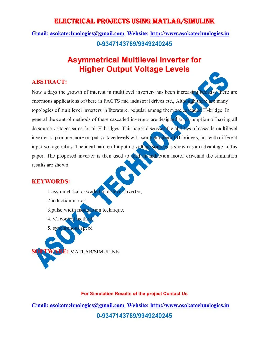
Now a days the growth of interest in multilevel inverters has been increasing because there are enormous applications of there in FACTS and industrial drives etc., Although there are many<br>topologies of multilevel inverters in literature, popular among them are cascaded H-bridge. In<br>general the control methods of these cascaded inverters are designed an assumption of having all dc source voltages same for all H-bridges. This paper discusses the abilities of cascade multilevel inverter to produce more output voltage levels with same number of H-bridges, but with different input voltage ratios. The ideal nature of input dc voltage sources is shown as an advantage in this paper. The proposed inverter is then used to feed an induction motor driveand the simulation results are shown<br>

E N D
ELECTRICAL PROJECTS USING MATLAB/SIMULINK ELECTRICAL PROJECTS USING MATLAB/SIMULINK Gmail:asokatechnologies@gmail.com, Website: http://www.asokatechnologies.in 0-9347143789/9949240245 Asymmetrical Multilevel Inverter for Higher Output Voltage Levels ABSTRACT: Now a days the growth of interest in multilevel inverters has been increasing because there are enormous applications of there in FACTS and industrial drives etc., Although there are many topologies of multilevel inverters in literature, popular among them are cascaded H-bridge. In general the control methods of these cascaded inverters are designed an assumption of having all dc source voltages same for all H-bridges. This paper discusses the abilities of cascade multilevel inverter to produce more output voltage levels with same number of H-bridges, but with different input voltage ratios. The ideal nature of input dc voltage sources is shown as an advantage in this paper. The proposed inverter is then used to feed an induction motor driveand the simulation results are shown KEYWORDS: 1.asymmetrical cascaded multilevel inverter, 2.induction motor, 3.pulse width modulation technique, 4. v/f control method, 5. synchronous speed SOFTWARE: MATLAB/SIMULINK For Simulation Results of the project Contact Us Gmail:asokatechnologies@gmail.com, Website: http://www.asokatechnologies.in 0-9347143789/9949240245
ELECTRICAL PROJECTS USING MATLAB/SIMULINK ELECTRICAL PROJECTS USING MATLAB/SIMULINK Gmail:asokatechnologies@gmail.com, Website: http://www.asokatechnologies.in 0-9347143789/9949240245 BLOCK DIAGRAM: Fig. I. Block Diagram Schematic ofY/f control ofYSI fed 3-phase Induction Motor Drive For Simulation Results of the project Contact Us Gmail:asokatechnologies@gmail.com, Website: http://www.asokatechnologies.in 0-9347143789/9949240245
ELECTRICAL PROJECTS USING MATLAB/SIMULINK ELECTRICAL PROJECTS USING MATLAB/SIMULINK Gmail:asokatechnologies@gmail.com, Website: http://www.asokatechnologies.in 0-9347143789/9949240245 EXPECTED SIMULATION RESULTS: Fig.2. Proposed asymmetrical cascaded multilevel inverter For Simulation Results of the project Contact Us Gmail:asokatechnologies@gmail.com, Website: http://www.asokatechnologies.in 0-9347143789/9949240245
ELECTRICAL PROJECTS USING MATLAB/SIMULINK ELECTRICAL PROJECTS USING MATLAB/SIMULINK Gmail:asokatechnologies@gmail.com, Website: http://www.asokatechnologies.in 0-9347143789/9949240245 Configuration with VllV12:Vll = lVDc:IVDc:IVDc Fig.3. Output wave form of 7-level inverter Configuration with Vll V12:Vll = 4VDC: 5VDC: 6VDC Fig.4. Output wave form of 23-level inverter : For Simulation Results of the project Contact Us Gmail:asokatechnologies@gmail.com, Website: http://www.asokatechnologies.in 0-9347143789/9949240245
ELECTRICAL PROJECTS USING MATLAB/SIMULINK ELECTRICAL PROJECTS USING MATLAB/SIMULINK Gmail:asokatechnologies@gmail.com, Website: http://www.asokatechnologies.in 0-9347143789/9949240245 Configuration with Vll V12:Vll = lVDc: 3VDc: 9VDc Fig.5. Output wave form of 27-level inverter For Simulation Results of the project Contact Us Gmail:asokatechnologies@gmail.com, Website: http://www.asokatechnologies.in 0-9347143789/9949240245
ELECTRICAL PROJECTS USING MATLAB/SIMULINK ELECTRICAL PROJECTS USING MATLAB/SIMULINK Gmail:asokatechnologies@gmail.com, Website: http://www.asokatechnologies.in 0-9347143789/9949240245 Fig.6.THO of the cascaded 7-level inverter Fig, 7, THO of the 23-1evel cascaded inverter Fig.8.THO of the cascaded 7-level inverter Fig, 9, THO of the 27-1evel cascaded inverter For Simulation Results of the project Contact Us Gmail:asokatechnologies@gmail.com, Website: http://www.asokatechnologies.in 0-9347143789/9949240245
ELECTRICAL PROJECTS USING MATLAB/SIMULINK ELECTRICAL PROJECTS USING MATLAB/SIMULINK Gmail:asokatechnologies@gmail.com, Website: http://www.asokatechnologies.in 0-9347143789/9949240245 Fig. l0 . Output wave fonn of speed characterstics of the induction motor Fig. 11. simulation output wave form of torque the induction motor characterstics of induction motor Fig. 12 Simulation output waveform of Stator currents For Simulation Results of the project Contact Us Gmail:asokatechnologies@gmail.com, Website: http://www.asokatechnologies.in 0-9347143789/9949240245
ELECTRICAL PROJECTS USING MATLAB/SIMULINK ELECTRICAL PROJECTS USING MATLAB/SIMULINK Gmail:asokatechnologies@gmail.com, Website: http://www.asokatechnologies.in 0-9347143789/9949240245 CONCLUSION: The simulation results show that in this paper 3- phase 23-level and 27-level asymmetrical cascaded H-bridge inverter are studied. The output voltage of three phase Asymmetrical 23-level CHB gives 23.51 % THD, whereas 27-level asymmetrical CHB gives 12.56% THD without PWM technique. Hence compared to 23-level CHB, a 27-level unequal de voltage ratios consists of minute number of harmonics and increased output voltage quality. Finally the proposed system is connected to induction motor for future industrial and automotive applications and the simulation results are shown. REFERENCES: [I] 1. A Santiago-Gonzalez, 1. Cruz-Colon, R. otero-De-leon, V. lopezSantiago, E.I. Ortiz- Rivera, " Thre phase induction motor drive using flyback converter and PWM inverter fed from a single photovoltaic panel," Proc. IEEE PES General Meeting, pp. 1-6,20 II. [2] M. A Vitorino et aI. , "An efficient induction motor control for photovoltaic pumping," IEEE Trans. Industrial Electron., vol. 54, no. 4, pp. 1162-1170, April. 2011. [3] ADiaz, R. Saltares, C. Rodriguez, R. F. Nunez, E.!. OrtizRivera, and 1. Gonzalez-Llorente, "Induction motor equivalent circuit for dynamic simulation," Proc. IEEE Electric Machines and Drive Conference, (lEMDC ), May 2009. [4] E. Babaei and S. H. Hosseini, "Charge balance control methods for asymmetrical cascade multilevel converters," in Proc. ICEMS, Seoul, Korea, 2007, pp. 74-79. [5] K. Wang, Y. Li, Z. Zheng, and L. Xu, "Voltage balancing and fluctuation suppression methods of floating capacitors in a new modular multilevel converter," IEEE Trans. Ind. Electron., vol. 60, no. 5, pp. 1943-1954, May 2013 For Simulation Results of the project Contact Us Gmail:asokatechnologies@gmail.com, Website: http://www.asokatechnologies.in 0-9347143789/9949240245