Download
1 / 8
80 likes | 89 Views
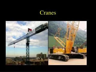
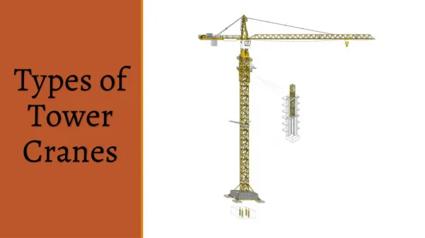
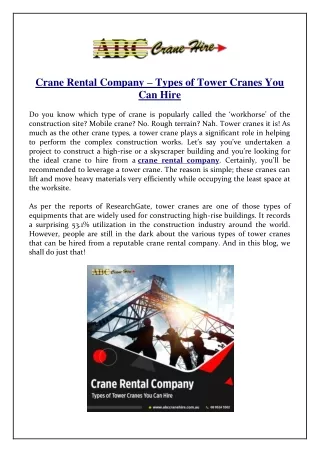
Top Slewing Tower Cranes make it possible to hoist and distribute loads by using 2 technologies: horizontal displacement of the trolley (MCT, MDT CITY, MDT, MD, MD MAXI ranges) or movement by raising the jib (MR range). With a growing client base all across the southwest we provide service, repair and inspections of all your cranes throughout the region, on any site.

E N D
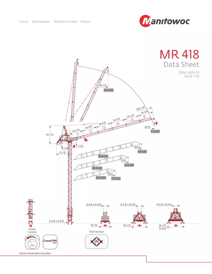
MR 418 Data Sheet FEM 1.001-A3 ASCE 7-10 87.3 ft 13.2 USt 200.3 ft 34.0 ft 34.0 ft 6 34.0 ft 5 34.0 ft 4 34.0 ft 197 ft 3 30.4 ft 2 5.5 USt 1 42.7 ft 6 7.2 ft 4 164 ft 4.3 ft 3 9.4 USt 31.3 ft 2 1 19.8 USt 6 3 131 ft 2 12.5 USt 1 26.5 USt 6 2 98 ft 1 26.5 USt 17.2 USt 8.0 ft x 8.0 ft 8.0 ft x 8.0 ft 8.0 ft x 8.0 ft 8.0 ft x 8.0 ft 19.7 ft 26.2 ft 26.2 ft 32.8 ft Power Control Top Tracing II - + Fleet kVA Values have been rounded
Mast 8.0 ft Y 800B FEM ASCE H (ft) P 802A H (ft) FEM ASCE 245.4 H (ft) H (ft) 13 FEM H (ft) FEM H (ft) 16.4 ft 16.4 ft 16.4 ft 10.9 ft 10.9 ft 229.0 16.4 ft 16.4 ft 16.4 ft 10.9 ft 10.9 ft 12 237.2 212.6 131 ft 164 ft 197 ft 226.4 210.0 193.6 6 7 7 6 4 3 - - - - - - 2 2 2 14 13 131 ft 164 ft 197 ft 229.0 217.8 201.4 7 6 6 5 4 3 - - - - - - - 2 2 11 10 226.4 220.8 14 196.2 179.8 163.4 147.0 130.6 114.2 97.8 81.4 65.0 210.0 204.4 13 12 12 9 8 193.6 188.0 11 10 177.2 11 10 171.6 155.2 138.8 122.4 106.0 89.6 73.2 56.8 40.4 7 6 160.8 144.4 128.0 116.8 106.0 89.6 73.2 56.8 40.4 9 8 ASCE H (ft) ASCE H (ft) 9 8 16.4 ft 16.4 ft 16.4 ft 10.9 ft 10.9 ft 5 16.4 ft 16.4 ft 16.4 ft 10.9 ft 10.9 ft 7 6 4 7 131 ft 164 ft 197 ft 220.8 204.4 188.0 5 4 3 8 8 8 - - - - - - - - - 131 ft 164 ft 197 ft 25.6 ft 6 3 2 1 5 5 4 4 3 2 3 2 1.0 ft 1 1 26.2 ft ZX 6830 FEM ASCE FEM H (ft) H (ft) H (ft) 16.4 ft 16.4 ft 16.4 ft 10.9 ft 10.9 ft 131 ft 164 ft 197 ft 164.7 159.1 148.3 7 8 7 1 1 - - - - - - - 2 - 2 175.5 159.1 142.7 126.3 109.9 93.5 77.1 60.7 175.5 159.1 142.7 126.3 109.9 93.5 77.1 60.7 10 10 9 8 9 8 7 6 7 6 H (ft) ASCE H (ft) 5 5 16.4 ft 16.4 ft 16.4 ft 10.9 ft 10.9 ft 4 4 JM 850 (32.8 ft) 131 ft 164 ft 197 ft 164.7 159.1 148.3 1 1 - - - - - - - 2 - 2 7 8 7 3 2 1 3 2 5.1 ft FEM H (ft) 16.4 ft 16.4 ft 16.4 ft 10.9 ft 10.9 ft 1 131 ft 164 ft 197 ft 282.5 271.3 260.5 5 6 6 5 4 2 4 4 4 - - - 1 - 2 19.7 ft JM 850 (32.8 ft) ASCE H (ft) 16.4 ft 16.4 ft 16.4 ft 10.9 ft 10.9 ft P 850US FEM ASCE H (ft) 131 ft 164 ft 197 ft 282.5 271.3 255.1 5 6 7 5 4 2 4 4 4 - - - 1 - - H (ft) FEM ASCE H (ft) FEM H (ft) 16.4 ft 16.4 ft 16.4 ft 10.9 ft 10.9 ft 293.3 293.3 H (ft) 16 16 276.9 260.5 244.1 227.7 216.5 276.9 260.5 244.1 227.7 216.5 265.1 248.7 237.9 7 7 8 5 4 4 131 ft 164 ft 197 ft 3 3 2 - - - 1 1 - 15 14 15 14 276.2 276.2 YM 850 (26.2 ft) 17 16 17 16 259.8 243.4 227.0 210.5 194.1 259.8 243.4 227.0 210.5 194.1 13 12 13 12 15 15 11 11 FEM H (ft) 205.7 189.3 172.9 156.5 140.1 123.7 107.3 90.9 74.5 58.1 205.7 189.3 172.9 156.5 140.1 123.7 107.3 90.9 74.5 58.1 16.4 ft 16.4 ft 16.4 ft 10.9 ft 10.9 ft 14 13 12 14 13 12 10 10 ASCE H (ft) 271.3 254.9 244.1 6 7 5 2 1 2 98 ft 131 ft 164 ft 6 5 4 - - - - - 2 9 8 7 6 9 8 7 6 16.4 ft 16.4 ft 16.4 ft 10.9 ft 10.9 ft 183.0 172.2 155.8 139.4 122.9 106.5 90.1 73.7 183.0 172.2 155.8 139.4 122.9 106.5 90.1 73.7 11 11 131 ft 164 ft 197 ft 265.1 248.7 237.9 7 7 8 3 3 2 5 4 4 - - - 1 1 - 10 9 10 9 197 ft 227.7 6 2 2 - 2 5 5 8 7 8 7 YM 850 (26.2 ft) 4 4 35.4 ft 3 2 3 2 6 6 ASCE H (ft) 5 5 16.4 ft 16.4 ft 16.4 ft 10.9 ft 10.9 ft 1 1 4 3 4 3 98 ft 131 ft 164 ft 260.5 249.6 238.7 6 5 4 1 1 1 - - - 2 1 - 5 6 7 1.6 ft 2 1 2 1 197 ft 222.3 2 1 - - 8 26.2 ft 32.8 ft 10.9 ft H1 = H H2 = H - 2.6 ft H3 = H - 3.9 ft Y 800B 16.4 ft - H1 = H H3 = H - 4.6 ft YM 850 - JM 850 = Non-reinforced mast = Reinforced mast 32.8 ft = K850 mast - H3 = H - 1.0 ft H1 = H ZX 6830 Note: When “ASCE” is noted in this data sheet it is referring to 115 mph Wind Zone, Exposure B, Design Wind Speed = 98 mph. See back cover for design wind speed calculations. MR 418
Anchorages (Consult us for ASCE 7-10 values) 98 ft P 802A H(ft) > 712.9 ft 712.9 ft 630.9 ft 532.5 ft 434.1 ft 587.6 ft 335.6 ft 489.2 ft 390.7 ft 237.2 ft 292.3 ft 193.9 ft 98 ft P 850US H(ft) > 762.1 ft 762.1 ft 647.3 ft 532.5 ft 401.2 ft 604.0 ft 489.2 ft 270.0 ft 357.9 ft 226.7 ft Load charts 197 ft 19 87 13.2 12.6 11.7 92 98 115 9.9 8.6 131 148 164 180 197 7.6 6.7 ft 6.1 5.5 USt 164 ft 17 77 79 82 85 92 98 115 118 - 131 11.2 9.8 8.7 USt 148 164 ft 19.8 19.5 18.7 18.0 16.5 15.3 13.0 13.2 11.9 10.5 9.4 USt 131 ft 14 62 26.5 24.8 22.5 20.5 19.6 18.8 17.4 16.1 13.7 66 72 79 82 85 92 98 115 124 - 131 11.8 USt ft 13.2 12.5 USt 98 ft 12 66 26.5 23.9 21.8 20.9 20.1 18.5 17.2 USt 72 79 82 85 92 98 ft 13.2 USt 3
Base ballast FEM ZX 6830 H (ft) 175.5 164.7 159.1 148.3 8.0 ft Y 800B YM 850 JM 850 H (ft) 245.4 229.0 217.8 201.4 H (ft) 271.3 254.9 244.1 227.7 H (ft) 293.3 282.5 271.3 260.5 (USt) 198.4 185.2 198.4 198.4 (USt) 133.4 133.4 155.4 177.5 (USt) 238.1 224.9 238.1 238.1 (USt) 224.9 224.9 224.9 238.1 98 ft 131 ft 164 ft 197 ft ASCE ZX 6830 (USt) 8.0 ft Y 800B YM 850 JM 850 H (ft) (USt) H (ft) H (ft) 260.5 249.6 238.7 222.3 (USt) H (ft) 224.9 211.6 224.9 224.9 (USt) 224.9 224.9 224.9 224.9 98 ft 131 ft 164 ft 197 ft 175.5 164.7 159.1 148.3 293.3 282.5 271.3 255.1 Jib weight & counter-jib ballast (in) 9700 lb 9700 lb (lb) (lb) 18,927 21,693 25,265 26,940 7 8 9 9 67,902 77,603 87,303 87,303 98 ft 131 ft 164 ft 197 ft 88 10 50 Luffing jib -33 ft -16 ft 0 16 ft 33 ft 49 ft 66 ft 82 ft 98 ft 115 ft 131 ft 148 ft 164 ft 180 ft 197 ft -49 ft 197 ft 19 ft 180 ft 90 ft 164 ft 17 ft 148 ft 75 ft 131 ft 14 ft 115 ft 61 ft 98 ft 12 ft 82 ft 47 ft 66 ft 49 ft 86° 33 ft 65° 16 ft 36 ft 25 ft 42 ft 33 ft 15° 16 ft 0 7 ft 31 ft 164 ft 131 ft 197 ft 98 ft 5.5 USt 12.5 USt 17.2 USt 9.4 USt MR 418
Component weights Crane upper : 197 ft - - 180LVF x 10 x 11 lb L (ft) W (ft) H (ft) (+/- 5%) h H Counter-jib (+ Hand rail + Platform) 21.1 20.8 6.9 9270 L l W W l Towerhead 8.4 6.9 38.8 12,236 L H h h H Ultra View 14.9 6.5 8.2 3605 Cab L l W h H 10.6 10.7 12.5 22,630 8.0 ft Pivot L W l h H Jib section 31.8 6.2 5.8 4850 L l W 34.5 34.5 34.5 34.5 34.4 6.2 6.2 6.2 6.2 6.2 5.8 5.8 5.8 5.8 6.1 2932 2855 2579 2304 4409 h H Jib section L W h H Pulley block 2.9 1.8 8.4 2601 L W h H 180 LVF 320 LVF 16.1 18.4 7.5 7.1 6.3 7.8 22,366 30,545 Hoisting winch (+ rope) L W l h H Luffing winch (+ rope) 150 VVF 16.0 5.6 7.1 11,100 W L l h H Rear left derrick arm (+ auxiliary winch + pulley block) 7.8 3.4 4.3 1356 l W L h H Front left derrick arm 11.5 1.4 1.6 419 W L l h H Articulated derrick arm 13.8 1.0 1.8 694 W L l h H Derrick support 6.5 3.6 7.4 1477 W L l 5
Component weights lb L (ft) W (ft) H (ft) (+/- 5%) h H 15.2 19.0 33.6 28,484 8.0 ft Climbing cage L W l 17.2 17.2 17.2 17.5 8.3 8.4 8.3 8.3 8.2 8.3 8.2 8.2 12,291 9017 7496 12,015 K 850/KR 849A KRMT 849A K 849A KMT 850.10A h H 8.0 ft l L W h H KRMT 849C 8.0 ft 11.7 8.4 8.3 7066 L l W h H Fixing angles P 802A 2.5 2..5 4.2 1050 W L l H Fixing angles P 850US 2.3 2.3 5.5 2127 L W h H Basic mast unit Y 800B 19.8 9.6 9.6 19,004 l W L h H Struts Y 800B 18.1 1.6 1.5 2447 L l W h H 1/2 Side member Y 800B 18.6 4.1 2.4 3351 L l W h H Side member Y 800B 39.4 4.1 2.4 6724 L l W h H Ballast support Y 800B 12.3 1.2 3.0 2392 L l W h H Chassis beam Y 800B 28.5 2.7 2.4 4938 L l W h H YM 850 JM 850 Central cross (transport position) 17.1 5.6 4.9 14,771 W L l h H YM 850 JM 850 Basic mast unit 28.7 8.2 8.2 32,187 L l W h H YM 850 JM 850 12.5 17.1 3.0 3.0 5.1 5.1 6173 7055 Chassis girder L l W h H YM 850 JM 850 Chassis ties 23.6 0.8 1.1 551 L W h H YM 850 JM 850 24.6 26.9 2.5 2.5 4.3 4.3 4630 5071 Struts W L l h H Cross girder ZX 6830 29.9 2.5 4.9 12,004 L l W h H Cross girder ZX 6830 29.9 3.7 3.6 11,607 W L l MR 418
Mechanisms 480 V - 60 Hz hp kW fpm USt fpm USt 184 13.2 331 13.2 240 9.9 427 9.9 341 6.6 581 6.6 571 3.3 797 4.2 689 2.4 833 3.3 92 26.5 166 26.5 123 19.8 213 19.8 174 13.2 312 13.2 312 6.6 399 9.9 344 5.8 417 8.4 180 LVF 120 Optima 320 LVF 120 Optima 180 132 1811 ft 320 240 2709 ft 1 min 15 s 150 110 150 VVF 56 RVF 162 Optima + 0 0.9 rpm 2 x 7.5 2 x 5.5 Y 800B RT 584 A1 - 2V fpm 28 - 56 8 x 8.4 8 x 6.2 ZX 6830 RT 664 A2B - 2V fpm 62 - 125 6 x 8.4 6 x 6.2 YM 850 JM 850 IEC 60204-32 180 LVF : 278 146 kVA 320 LVF : 390 202 kVA - + 480 V (+6% -10%) 60 Hz kVA Key Container High Cube 40 ft, and/or Flat Rack 20 ft Standard equipment Options Tightened anchorage frame Reactions in service Loosened anchorage frame Reactions out of service Hoisting Weight without load, without ballast, with jib and max. height Luffing Jib weight Slewing Total ballast weight Travelling Jib articulation axis Required power Power Control function: Hoisting speeds adapted to the available power - + Weathervaning position kVA Truck 44 ft Consult us 7
Notes Manitowoc Cranes Regional Headquarters Note: These mast combinations meet the EN 14439 and ASME B30.3-2012 specifications for “out of service” wind conditions, provided the illus- trated wind speed matches required design wind for the location of the tower crane. The “out of service” design wind speed was determined in accordance with ASCE 7-10, Figure 26.5-A. The wind velocity, used for this configuration was 98 mph (158 kph), which represents a nominal design 3-second wind gust at 33 ft (10 m) above ground for Exposure B category A. Factor of 0.85 was applied to the 50-year ultimate design wind speed of 115 mph (185 kph), per ASCE 37-02, with the assumption that this crane is considered a temporary structure used during a construction period of 2 years or less. Americas Manitowoc, Wisconsin, USA Tel: +1 920 684 6621 Fax: +1 920 683 6277 Shady Grove, Pennsylvania, USA Tel: +1 717 597 8121 Fax: +1 717 597 4062 Europe, Middle East, Africa Dardilly, France Tel: +33 472 18 2020 Fax: +33 472 18 2000 Constant improvement and engineering progress make it necessary that we reserve the right to make specification, equipment and price changes without notice. Illustrations shown may include optional equipment and accessories, and may not include all standard equipment. China Shanghai, China Tel: +86 21 6457 0066 Fax: +86 21 6457 4955 Greater Asia-Pacific Singapore Tel: +65 6264 1188 Fax: +65 6862 4040 Potain MR 418 Code 14-002-.5M-0214 www.manitowoccranes.com © Manitowoc 2014