Download
1 / 7

E N D
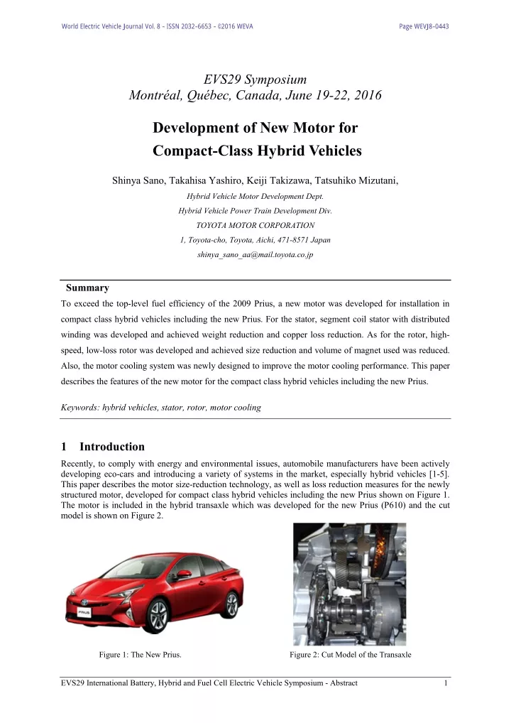
World Electric Vehicle Journal Vol. 8 - ISSN 2032-6653 - © 2016 WEVA Page WEVJ8-0443 EVS29 Symposium Montréal, Québec, Canada, June 19-22, 2016 Development of New Motor for Compact-Class Hybrid Vehicles Shinya Sano, Takahisa Yashiro, Keiji Takizawa, Tatsuhiko Mizutani, Hybrid Vehicle Motor Development Dept. Hybrid Vehicle Power Train Development Div. TOYOTA MOTOR CORPORATION 1, Toyota-cho, Toyota, Aichi, 471-8571 Japan shinya_sano_aa@mail.toyota.co.jp Summary To exceed the top-level fuel efficiency of the 2009 Prius, a new motor was developed for installation in compact class hybrid vehicles including the new Prius. For the stator, segment coil stator with distributed winding was developed and achieved weight reduction and copper loss reduction. As for the rotor, high- speed, low-loss rotor was developed and achieved size reduction and volume of magnet used was reduced. Also, the motor cooling system was newly designed to improve the motor cooling performance. This paper describes the features of the new motor for the compact class hybrid vehicles including the new Prius. Keywords: hybrid vehicles, stator, rotor, motor cooling 1Introduction Recently, to comply with energy and environmental issues, automobile manufacturers have been actively developing eco-cars and introducing a variety of systems in the market, especially hybrid vehicles [1-5]. This paper describes the motor size-reduction technology, as well as loss reduction measures for the newly structured motor, developed for compact class hybrid vehicles including the new Prius shown on Figure 1. The motor is included in the hybrid transaxle which was developed for the new Prius (P610) and the cut model is shown on Figure 2. Figure 1: The New Prius. Figure 2: Cut Model of the Transaxle EVS29 International Battery, Hybrid and Fuel Cell Electric Vehicle Symposium - Abstract 1
World Electric Vehicle Journal Vol. 8 - ISSN 2032-6653 - © 2016 WEVA Page WEVJ8-0444 2Development Objectives The development objectives of the new hybrid motor for compact-class vehicles were size/weight reduction and fuel efficiency improvement. Figure 3 shows the motor size and loss reduction of the P610 and motor developed for 2009 Prius (P410). Compared to P410, the P610 reduced loss 20% in JC08 mode. The motor size was reduced 35% and increased the power density up to 36% shown on Figure 4. Figure 3: Motor Size and Loss Comparison of P410 and P610 Figure 4: Motor Size and Power Comparison of P410 and P610 These objectives were achieved through renovated gear train, new stator development, new rotor development and motor cooling. 2.1Basic Specifications and Structure Figure 5 shows the main cross section of the P410 hybrid transaxle developed for the 2009 Prius and figure 6 shows the new P610 hybrid transaxle. The basic structure of the gear train was comprehensively renovated by adopting a motor reduction device using parallel shaft gears and a dual-axle motor structure. These features were then combined with motor size reduction achieved through use of a high-reduction motor. The specification of new motor (P610) and the motor developed for 2009 Prius (P410)[6] is listed in Table 1. The motor reduction device of the P410 hybrid transaxle used a planetary gear system, where as the newly developed transaxle uses parallel shift gears. As the reduction device was simplified, its structural limitations were reduced. This widened the range over which the reduction ratio could be set, making it possible to secure a greater reduction ratio. Increasing reduction ratio made it possible to increase motor speed and reduce motor torque, as shown in Figure 7, helping reduce motor size. EVS29 International Battery, Hybrid and Fuel Cell Electric Vehicle Symposium - Abstract 2
World Electric Vehicle Journal Vol. 8 - ISSN 2032-6653 - © 2016 WEVA Page WEVJ8-0445 Power Split Device Generator Motor Motor Reduction Gear Figure 5: P410 Cross Section Figure 6: P610 Cross Section Table 1: Specifications of New Drive Motor P610 P410 Transaxle Vehicle Class Compact 1.8 L Displacement Max. Power Max. Torque Type Max. Power Engine 70 kW 73 kW 142 Nm Synchronous AC motor 53 kW 163 Nm 17000rpm Motor 60 kW 207 Nm 13500rpm Max. Torque Max. Speed Motor Reduction Gear Ratio Differential Gear Ratio Weight Including ATF Overall Length 3.118 2.636 3.476 3.267 -5.6 kg - -47 mm - Figure 7: Downsizing of Motor EVS29 International Battery, Hybrid and Fuel Cell Electric Vehicle Symposium - Abstract 3
World Electric Vehicle Journal Vol. 8 - ISSN 2032-6653 - © 2016 WEVA Page WEVJ8-0446 2.2New Stator Development Round wires were used for the stator of the P410 drive motor shown in Figure 8. A segment coil stator with distributed winding was developed for the drive motor shown in Figure 9. The main features of this stator are as follows: (1) Newly developed distributed winding aimed at increasing the high space factor and reducing loss. Switching from round wires to rectangular wires improved the space factor by at least 15%. Additionally, reducing coil wire usage through segment winding helped reduce weight and copper loss. (2) Newly developed coil wire suitable to segment winding. To improve the winding space factor, a new coating material was developed that can handle high voltage in thin film and offers improved weldability and processability. Figure 8: Drive Motor for P410 Figure 9: Drive Motor for P610 2.3New Rotor Development A new high-speed, low-loss rotor was developed. To support the high-speed rotor shown in Figure 10, a locknut method was adopted for tightening the core. Motor size reduction was achieved through measures such as an increase in rotation speed. Furthermore, a magnetic circuit design was developed that improved the reluctance torque of the rotor core. As a result, the volume of magnet used was reduced by at least 15% compared with the P410. As for reducing loss, the harmonic component of the magnetic flux was substantially reduced by optimizing magnet position, thereby reducing iron loss. Furthermore, a thin electromagnetic steel plate and a new magnet material were developed, reducing motor loss and the usage of rare earth material. Figure 10: P610 Drive Rotor EVS29 International Battery, Hybrid and Fuel Cell Electric Vehicle Symposium - Abstract 4
World Electric Vehicle Journal Vol. 8 - ISSN 2032-6653 - © 2016 WEVA Page WEVJ8-0447 By changing the magnet layout from P410 to the layout of P610 shown on Figure 11 the wave of the magnetic flux density became closer to the fundamental harmonic thus making the motor more quiet. The magnetic flux density wave for P410 is shown on Figure 12 and magnetic flux density wave for P610 is shown on Figure 13. Also, the motor efficiency was increased substantially from reducing the third and fifth harmonic.The motor efficiency map of P610 is shown on Fig.14 P410 P610 Figure 11: Rotor Permanent Magnet Layout Figure 12: magnetic flux density wave of P410 Figure 13: magnetic flux density wave of P610 Figure 14: Motor Efficiency map of P610 EVS29 International Battery, Hybrid and Fuel Cell Electric Vehicle Symposium - Abstract 5
World Electric Vehicle Journal Vol. 8 - ISSN 2032-6653 - © 2016 WEVA Page WEVJ8-0448 2.4Motor Cooling To improve the motor cooling performance, the motor cooling system was newly designed. In the conventional motor cooling structure, the motor is cooled by ATF scraped up by the gears shown in Figure 15. An oil catch tank mounted at the topside of the transmission case collects the ATF pumped up by gears. The trapped oil is distributed to the motor and generator sides, and dripped onto the coil ends shown on Figure 16. Figure 15: Diagram of Oil Flow for P410 Figure 16: Diagram of Motor Cooling for P410 In the P610, cooling efficiency has been improved by supplying some of the oil being circulated by the pump directly to the motor. Figure 17 shows the motor cooling structure. The oil pump is positioned inside the transaxle. ATF for cooling the motor travels through the oil channel provided in the rear cover and is cooled by the oil cooler installed on the transaxle. It is then supplied to the upper part of the case. From there, ATF is supplied to the stator and coil end through the inner pipe, promoting heat dissipation from the stator to the case via ATF. Thus, the motor is cooled efficiently and increased the cooling potential up to 58% compared to P410 to match the decrease in motor size and increased current density shown on Figure 18. Furthermore, the rotor core cooling structure actively cools the magnet. By significantly reducing the temperature of the magnet through cooling performance improvement, the volume of rare earth element used was reduced. Rotor core cooling contributed to the reduction of rare earth element up to 85% compared to the P410 which was achieved through new magnet material, new magnet layout, and motor cooling. Figure 17: Conceptual diagram showing motor cooling Figure 18: Current Density and Motor Size EVS29 International Battery, Hybrid and Fuel Cell Electric Vehicle Symposium - Abstract 6
World Electric Vehicle Journal Vol. 8 - ISSN 2032-6653 - © 2016 WEVA Page WEVJ8-0449 3Conclusion A new motor was developed for installation in compact class vehicles including new Prius. For the stator for drive motor, segment coil stator with distributed winding was developed and achieved weight reduction and copper loss reduction. As for the rotor, high-speed, low-loss rotor was developed and achieved size reduction and volume of magnet used was reduced 15%. Newly developed magnet material, new magnet layout, and newly designed motor cooling system reduced volume of rare earth element usage by at least 85%. As a result, the motor size was reduced 35% compared to P410, and reduced the loss upon JC08 mode up to 20% compared to P410. References [1] S. Abe, S. Sasaki, H. Matsui, K. Kubo. Development of Mass-produced Hybrid System for Passenger Vehicles: 975, pre-printed papers of the academic lecture meeting, Society of Automotive Engineers of Japan, Inc., Oct. 1997 [2] S. Sasaki, T. Takaoka, H. Matsui, T. Kotani. Toyota's Newly Developed Electric-Gasoline Engine Hybrid Power Train System: EVS-14, Dec. 1997 [3] M. Matsui, K. Kondo, R. Ibaraki, H. Ito. Development of Trans-axle for Hybrid Vehicles. Motor Technolgy Vol. 52, No. 9, 1998 [4] K. Takizawa, M. Kamiya, T. Mizutani, H. Hata. New Hybrid Transmission: EVS-21, Apr. 2005 [5] M. Adachi, T. Mikami, K. Yagi, S. Wakuta. Development of a New Hybrid Transmission for GS450: EVS- 22, Oct. 2006 [6] A. Takasaki, T. Mizutani, K. Kitagawa, T. Yamahana, K. Odaka, T. Kuzuya, Y. Mizuno, Y. Nishikawa. Development of New Hybrid Transmission for 2009 Prius: EVS-24, May 2009 Authors Shinya Sano Keiji Takizawa Hybrid Vehicle Motor Development Dept. Hybrid Vehicle Motor Development Dept. Hybrid Vehicle Power Train Development Div. Hybrid Vehicle Power Train Development Div. TOYOTA MOTOR CORPORATION TOYOTA MOTOR CORPORATION Takahisa Yashiro Tatsuhiko Mizutani Hybrid Vehicle Motor Development Dept. Hybrid Vehicle Motor Development Dept. Hybrid Vehicle Power Train Development Div. Hybrid Vehicle Power Train Development Div. TOYOTA MOTOR CORPORATION TOYOTA MOTOR CORPORATION EVS29 International Battery, Hybrid and Fuel Cell Electric Vehicle Symposium - Abstract 7