Download
1 / 24
300 likes | 692 Views
JWST-PRES-012899. James Webb Space Telescope Systems Overview May 2009 Partners Workshop. Mike Menzel GSFC Mission Systems Engineer. Topics. Technical Accomplishments Since the Last Partners Workshop Updates to System Baseline System Architecture Updates Data Compression

E N D
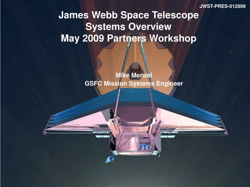
JWST-PRES-012899 James Webb Space TelescopeSystems OverviewMay 2009 Partners Workshop Mike Menzel GSFC Mission Systems Engineer
Topics • Technical Accomplishments Since the Last Partners Workshop • Updates to System Baseline • System Architecture Updates • Data Compression • Observatory to Launch Vehicle Clocking Angle • Observatory Updates • Stray Light Mitigations • Thermal Recovery Updates • Sunshield Membrane Management Subsystem Updates • System Performance and Resource Margins • Issues • Future Work and Summary
Technical Accomplishments Since the Last Partners Workshop • Systems Engineering (SE) participated in the following reviews: • Review of MIRI Verification Model Test Results December 2nd and 3rd 2008 • The Sunshield Membrane Management Delta PDR February 4th and 5th 2009 • ISIM Thermal CDR February 10th 2009 • The Core Test Article Test Readiness Review February 25th 2009 • ISIM Systems CDR March 2nd thru 6th 2009 • The IT&T Optical Ground Support Equipment CDR March 23rd thru 27th 2009 • The Propulsion Subsystem PDR April 14th 2009 • SE completed work to address: • System Data Volume / Data Compression Recovery • Observatory Thermal Performance Recovery • Cryogenic Radiator Margins • Cryo-Cooler Cool-Down Margins • Observatory to Launcher Clocking Angle and 5th Coupled Loads Analysis Evaluation
Communications Coverage Provided For all Critical Events • Observatory Deployments • Solar Array • High Gain/ Medium Antennas • Sunshield • Optical Telescope Element L2 Point Ariane 5 Upper Stage Injects JWST Into Direct Transfer Trajectory Observatory – Upper Stage Separation L2 Lissajous Orbit L2 Transfer Trajectory S-Band Tlm Link ( 2Kbps) S-Band Cmd Link (0.25 Kbps) S-Band Ranging Ariane 5 Launch System One 4 Hour Contact with the Ground Every 12 Hours Ka-Band Science Link ( Selectable 7, 14, 28 Mbps) S-Band Tlm Link (Selectable 0.2 - 40 Kbps) S-Band Cmd (Selectable 2 and 16 Kbps) S-Band Ranging S-Band Tlm Link ( 2Kbps) S-Band Ranging Observatory / LV Clocking Angle Deep Space Network Communications Services for Launch (TDRS, ESA, …) Space Telescope Science Institute Science & Operations Center NASA Integrated Services Network Ariane PPF S5 GSFC Flight Dynamics Facility JWST System Architecture Updates
Analysis of the ISIM data compression algorithms found that large scale pixel-to-pixel variations in the NIR detectors (shown to the right) caused significant degradation of the compression performance. JWST data system volume was sized assuming ISIM would provide 2:1 lossless data compression. The algorithms were only meeting a 1.1:1 lossless compression ratio. A Data Compression Working Group was formed to address this data volume issue. The group recommended correcting the problem by doubling contact time with the Deep Space Network, going from one 4 contact every 24 hours to one 4 hour contact every 12 hours. This approach not only solved the data volume but offered other advantages: More frequent insight into Observatory state of health, momentum management status, science observation status, etc which increased opportunities for responses and / or re-planning Data would be available 12 hours earlier Could improve ability to respond to Targets of Opportunity. MSE presented this plan to the Science Working Group (SWG) on 1/29/09. There were no objections from the SWG. The Project and SE have been exploring options for Observatory changes to enable ground station scheduling flexibility. Increased recorder capacity Increased downlink data rate Data Compression Issue Large scale structure in the bias of the H2RG SCA
XLV D Observatory-to-Launch Vehicle Center of Gravity (1 of 2) • Lateral offset Center of Gravity (CG) of stowed Observatory shown on the right is not within bounds of Ariane 5 User’s Manual (A5UM). • Arianespace provided feedback on the allowable CG area which it is willing to sign on to at this time. • The solid red box below shows this area in LV Z-Y Coordinates. • The blue box on the right illustrates additional area that the project will seek to negotiate to account for residual uncertainties. • Systems Engineering is currently holding ~80 kg of mass reserve for potential ballast to ensure compliance with these requirements.
SE investigated alternate observatory orientations relative to the Launch Vehicle (LV) to gain CG margin and to free up mass reserves currently “ear-marked” for ballast. The study concluded that a clocking angle of 235 was an optimum choice, as opposed to the current baseline angle of 25. Clocking is illustrated in the figure to the right. The trends for CG growth have all been toward the -J1 direction. Arianespace has provided coupled loads analysis at these two angles. SE is currently evaluating these loads. Observatory-to-Launch Vehicle Center of Gravity (2 of 2)
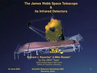
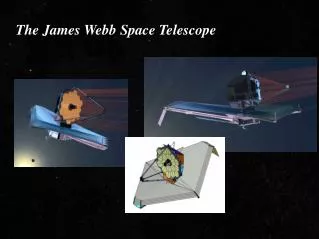
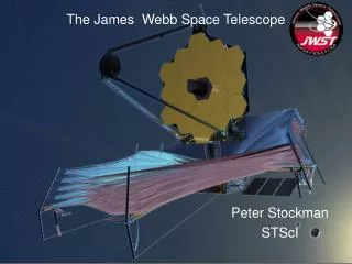
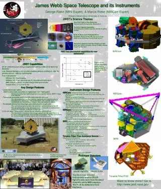
Optical Telescope Element (OTE) diffraction limited at 2 micron wavelength. 25 m2 , 6.35 m average diameter aperture. Instantaneous Field of View (FOV) ~ 9’ X 18’. Deployable Primary Mirror (PM) and Secondary Mirror (SM). 18 Segment PM with 7 Degree of Freedom (DOF) adjustability on each. Integrated Science Instrument Module (ISIM) containing near and mid infrared cryogenic science instruments The NIRCam SI functions as the on-board wavefront sensor for initial OTE alignment and phasing and periodic maintenance. Deployable sunshield for passive cooling of OTE and ISIM. Mass: < 6330 kg . Power Generation: 2000 Watts Solar Array. Data Capabilities: 471 Gbits on-board storage Science Data Downlink: 28 Mbps. Life: Designed for 11 years (goal) of operation. JWST Observatory Summary 6.100 m Deployed Configuration 6.600 m 14.625 m 21.197 m Stowed Configuration 10.661 m 4.472 m
Optical Telescope Element (OTE) • 6 meter Tri-Mirror Anastigmatic • 18 Segment Primary Mirror • Integrated Science Instrument Module (ISIM) • Located inside an OTE provided ISIM Enclosure • Contains 4 Science Instruments (NIRCam, NIRSpec • MIRI, FGS / TF) OTE Backplane / ISIM Enclosure • Thermal Region 1 • Components cooled to • cryogenic temperatures • Thermal Region 2 • Components maintained at • ambient temperatures on cold • side of the observatory OTE Secondary Mirror Aft Optics Subsystem ISIM Electronics Compartment (IEC) OTE Primary Mirror OTE Deployment Tower SS Layer 5 SS Layer 1 Momentum Trim-Tab • Sunshield (SS) • 5 layers to provide thermal • shielding to allow OTE and ISIM • to passively cool to required • cryogenic temperatures Solar Array • Spacecraft Bus • Contains traditional • “ambient” subsystems Thermal Region 3 - Components maintained at ambient temperatures The JWST Observatory Elements and Regions
Improvements in the observatory’s susceptibility to stray light: Modifications made to the OTE “BIB” thermal shield have improved the MIR stray-light. Modifications to the OTE “Frill” have improved NIR “Truant” Path Stray Light levels. Cryogenic radiator margins experienced a significant decline due to changes in the BSF thermal model, which our design was extremely sensitive to. The margin levels were recovered and the sensitivity of the design improved by modifications in the “Core” region of the observatory that involved: Shielding of the IEC Improvements in the Sunshield Thermal Closeout around the DTA Selective removal of thermal insulation of the BSF. Improvements in the Cool-Down Margins of the MIRI Cryo-Cooler system were achieved by: Shielding of the MIRI Cooler RLDA Incorporation of a Radiative Shield around MIRI. The Sunshield Membrane Management Subsystem under went a redesign which improved its deployment reliability. The Membrane Release Devices were modified to be initiated electronically rather than mechanically. OTE “Frill” Cryogenic Radiators OTE “BIB” MIRI Radiative Shield Sunshield Membrane Management Subsystem Backplane Support Frame (BSF) • Observatory Core Area • ISIM Electronics Compartment (IEC) • Sunshield Close-Out • Deployed Tower Assembly • MIRI Cryo-Cooler Refrigerant Deployed • Line Assembly (RLDA) Observatory Changes Since the Last Partners Workshop
Updates to Stray Light Mitigations • SE completed studies to implement a new BIB design to address concerns of the sensitivity of MIRI stray light to BIB temperatures. • ~1K changes in BIB temperature could have consume the MIRI stray light margin at 20 microns. • The new design increased the OTE Frill to provide the means of blocking thermal emissions from the “hot” observatory CORE region. • The Frill runs at much lower temperature than BIB. (roughly equal to PM temperature, at about 50K) • The BIB was made smaller. • The system improved the MIR stray light and its sensitivity to BIB / Frill temperatures, and: • Improved CORE temperatures • Offered decrease in mechanical complexity associated with the deployment of the previously large BIB • Offered potential mass savings ~10kg (TBR). Previous BIB Design Modified Frill New Reduced BIB Design Use or disclosure of data contained on this page is subject to the restriction(s) on the title page of this document.
In February of 2009, the observatory thermal model was updated with a high fidelity model of the BSF. Significant decline of cryogenic radiator margins were computed. BSF thermal conductivity had increased This illustrated the sensitivity of the design to this parameter. A Thermal Margin Recovery Team addressed the problem, by minimizing heat loads into the BSF at their sources. The team gave their final presentation on 4-8-09, with a follow-up presentation on April 4-15-09. The team proposed the following observatory modifications for incorporation into the baseline: A three MLI layer closeout of the Observatory Core Region with perforations in the Sunshield Hub to allow radiation of heat out from the core to the sunshield edges. A extended 2 layer conformal shield around the ISIM Electronics Compartment (IEC). Selective removal of insulation around the Optical Telescope Element (OTE) Backplane Support Frame (BSF). The GSFC Team will continue work to improve the IEC baffle performance. Observatory Cryogenic Radiator Margin Recovery (1 of 2) A 3 MLI Close-Out of the Core Region Using the Existing Deployed Tower Assembly Perforated Sunshield Hub Selective BSF MLI/SLI IEC Extended Conformal
Observatory Cryogenic Radiator Margin Recovery (2 of 2) • Given these modifications the team predicted the following thermal performance with the estimated effects of liens and opportunities included: • NIRCam Radiator Margin: 58.6% • NIRSpec OA Radiator Margin: 56.9% • NIRSpec FPA Radiator Margin: 64.5% • FGS Radiator Margin: 65.5% • MIRI Radiator Margin: 86.5% • The table below gives the breakdown between estimate from model v4.1a, Liens, Threats and Opportunities as determined by GSFC. • These predicts do not include potential benefits from future baffle improvement and additional margin from detector temperature requirements relaxation. • Sensitivity studies conducted during this effort, indicate a potential for baffle modifications to bring all radiator margins over 60%. • The impact of these changes on thermal stability will now need to be assessed very carefully as part of the CDR Integrated Modeling Cycle. • SE is now focusing its efforts on developing the mechanical design of these concepts.
The MIRI Cryo-Cooler is a hybrid cooling system consisting of a Pulse Tube Pre-Cooler and Joule Thomson final cooler. The cooler cools the MIRI detector to ~6K The compressors are located in the spacecraft bus. Refrigerant lines traverse Region 2 of the observatory, and cool the MIRI detector and Optics Module in Region 1. Refrigerant Lines Deployed Assembly (RLDA) Estimates for heat loads result in inadequate margins on the MIRI Cryo-Cooler cool-down margins (aka Pinch Point). Pinch point occurs at the crossover point in cooling from the Pulse Tube pre-cooler to the Joule-Thomson Cooler. It is a point in the cool-down where performance is least efficient. The minimum margin level that would be acceptable for flight was reviewed and defined by the Cryo-Cooler Team and SE: 35% at launch (25% load margin + 10% lift margin) Principal heat loads are from: MIRI Optics Module (OM). Observatory thermal loads on the refrigerant lines MIRI Cryo-Cooler Cool-Down Margin (1 of 2) • The MIRI Verification Model Tests showed the MIRI OM heat loads had acceptable margin. • The observatory has been working to lower its thermal loads on the RLDA in conjunction with its thermal recovery efforts.
MIRI Cryo-Cooler Cool-Down Margin (2 of 2) • The observatory has incorporated a deployed shower curtain like radiation shield around the RLDA to decrease radiative loads as shown below. • Shower curtain open direction and angular measure (+V2 and 90º in figure below). • The shield deployment concept is shown on the lower right. DEPLOYED 8” View to Space STOWED Shower curtain with 90º opening facing +V2 direction
To provide additional system level heat load margin, the Project directed the ISIM to incorporate a radiation shield around the MIRI Instrument in late November of 2008. ISIM has completed trades to formulate a concept for this shield, and presented their results at a Concept Review on 5/12/09. The shield uses the 18K stage of the cryo-cooler to actively cool a portion of it, trading the increased heat load on the 18K for a drop in 6K heat load. Their selected concept shown on the upper right consists of the following: Single Al panel actively cooled by the Cryo-Cooler 18K stage, black on the inside Structural frame conductively tied to the cooled panel Multi-Layer Insulation (MLI) supported by the structural frame. (Single Layer Insulation may be used instead of MLI) Thermal isolating struts to mount to the ISIM structure Predicted mass 24.57 kg which includes 24% contingency. The location of the shield around MIRI on the ISIM is shown on the lower right. The system yields a savings of ~30mW at the 6K stage in exchange for an increase of ~55mW at the 18K stage The increase in 18K heat load appears easily offset by the additional heat lift afforded by the reduction in 6K heat lift MIRI Radiation Shield Actively Cooled Al Panel MLI Not Shown Al Structural Frame Isolation Mounts MIRI Radiation Shield On ISIM
The Core Thermal Balance Test • The Core Test Article integration has been completed, the article was installed into the M4 Thermal Vacuum Chamber completed as illustrated below: • OTE/SC assemblies mated • Test article moved to the M4 chamber lid • GSFC radiometers received and installed • He shroud installed, leak checks completed • MLI closeouts complete • Instrumentation installation and checkout complete • As of May 13th the cool-down was following the expected profile. Core Test Article Installation on Chamber Lid He Shroud Installation
Sunshield Membrane Management Subsystem (1 of 2) • The Sunshield Membrane Management Subsystem (MMS) consists of the covers, and mechanisms which control the deployment of the five Sunshield Membranes. • This subsystem trades complexity against the advantages of a controlled / deterministic membrane deployment • The Sunshield MMS was deemed too complex and not at Preliminary Design Review level of maturity at the Sunshield PDR. The review board determined a delta review of this subsystem was necessary. • The Standing Review Board (SRB) also gave the Project the action to address their concern that the baseline for the verification of the sunshield deployment was not sufficient given this level of complexity. Sequenced Release of Thru-Ties to Minimize “Loose” Membrane During Deployment
The Sunshield Team redesigned the MMS and held a successful Delta PDR for this subsystem on 2/4/09. The MMS included re-design of: Covers which protect the membranes during launch and ascent. Core area restraint devices. Membrane release mechanisms (springs, magnets, ect) which provide a controlled un-furling of the membranes. The 108 Membrane Release Devices (MRD)s which hold the membranes and their covers in place, as well as a re-look at their distribution over the sunshield. Following this review, a subsequent trade study recommended adopting an electrical initiation of the MRD’s which further improved their reliability and robustness for test and integration. Now that the MMS architecture has been determined the team is addressing the SRB concerns to find the optimal way to validate / verify deployment. Sunshield Membrane Management Subsystem (2 of 2) Membrane Covers STOWED MRD Constrain Cover & Provide Sequence Deployment
Performance / Resource currently meeting requirement with sufficient margin Performance currently meeting its requirement, with low margin. Performance currently not meeting its requirement Performance / Resource Parameter Status Note: WFE’s are cited at yellow at this pending the resolution of NIRCam WFE Issues. JWST_ISIM.May.MPR/21
Observatory Mass Margins • Observatory mass margins are low, but still manageable by Mission Systems Engineering (MSE). Following the conclusion of the thermal recovery effort, Observatory Systems Engineering (OSE) and MSE will have to refocus efforts on mass reduction. • The thermal recovery measures have had unexpectedly small impacts on the mass of the observatory, (of the order 10 to 20 kg TBR). • A favorable outcome of the Observatory – to – LV clocking trade will greatly enhance the management of the mass reserves by eliminating the 80 kg currently ear-marked for ballast. • The table below from the April 30, 2009 Mass Report (09-JWST-0183) shows: • Margin without pendings: (6530 - 5751) / 5751 = 13.5% • Margin with pendings: (6530 – 5897) / 5897 = 10.7% • The GSFC GOLD Rules applied at the subsystem level requires a mass margin of 11.1% at CDR.
Summary and Future SE Efforts • The Thermal Recovery Team has found solutions which bring system thermal margins back to acceptable levels, and improve the sensitivity of the thermal design. • The Core Article Thermal Test will add to our insights into these sensitivities. • The Sunshield MMS Team has made excellent progress in improving their design in terms of its complexity, robustness to integration and test and reliability. • This team and SE are now focused on closing the deployment validation / verification approach. • Mass reserves are low, but are still deemed as manageable. • A successful outcome to the Observatory Clocking Trade greatly enhance our ability to manage these mass reserves. • Wavefront error reserves will need to be managed very carefully against pending risks. • NIRCam WFE Performance • OTE WFE Risks • Observatory Thermal and Dynamic Stability • SE has formulated a roadmap to a March 2009 Mission CDR, that it will vet during one of the splinter sessions of this Partners Workshop.