Download
1 / 9
90 likes | 105 Views
Low Noise Infrared Detector. Grace Jung, Travis Tanaka. Goal: To detect and amplify a small IR DC signal through background. Problem: It is hard to build large gain DC Amplifiers with low Input Offset Voltage 1/f Noise Solution…. Chopper Amplifier.

E N D
Low Noise Infrared Detector Grace Jung, Travis Tanaka
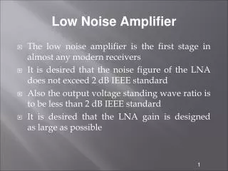
Goal: To detect and amplify a small IR DC signal through background. • Problem: It is hard to build large gain DC Amplifiers with low • Input Offset Voltage • 1/f Noise • Solution…
Chopper Amplifier • 1949 – Edwin A. Goldberg designed chopper-stabilized amplifier • Principle: The input DC signal is “chopped” and thus converted to AC. Then the AC signal is amplified, and these outputs are integrated back together to recover the original signal.
Parts List • Switch Parts • 4066 Analog Switch • Inverter • IR Detector/Emitter • LTR301 IR Phototransistor • LTE302 IR Emitter • 3x 1 µF • 10MΩ • 100kΩ • 10kΩ • 1kΩ • 270Ω • 100Ω • 10Ω • 2x LM411 opamp • DC Power Supply • Oscilloscope
What we did (1) • Digikey shipping delays so we just got the parts yesterday evening. • We built the circuit and substituted the IR emitter/detector pair for room lights and a MRD3051 phototransistor.
WHAT WE DID (2) Photodiode Input Chopper Circuit Output
Plans for Final Presentation • Swap in IR Emitter and Receiver • Fix saturation issues • The output is the same for the phototransistor covered or uncovered. • Might just be fixed by switching to IR parts since the IR output voltage is ~0.1mV vs MRD3051 output of ~10mV
Summary • Goal: Detect and amplify small IR signal through background • Plan: Use chopper amplifier to minimize noise while providing high gain • What we did: • Built circuit with MRD3051 phototransistor • To do (before final): • Implement IR devices • Fix saturation issues