Download
1 / 115
1.48k likes | 3.18k Views
Low-Noise Amplifier. RF Receiver. Antenna. BPF1. LNA. BPF2. Mixer. BPF3. IF Amp. Demodulator. RF front end. LO. Low-Noise Amplifier. First gain stage in receiver Amplify weak signal Significant impact on noise performance Dominate input-referred noise of front end

E N D
RF Receiver Antenna BPF1 LNA BPF2 Mixer BPF3 IF Amp Demodulator RF front end LO
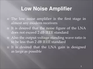
Low-Noise Amplifier • First gain stage in receiver • Amplify weak signal • Significant impact on noise performance • Dominate input-referred noise of front end • Impedance matching • Efficient power transfer • Better noise performance • Stable circuit
LNA Design Consideration • Noise performance • Power transfer • Impedance matching • Power consumption • Bandwidth • Stability • Linearity
Noise Figure • Definition • As a function of device G: Power gain of the device
NF of Cascaded Stages Sin/Nin Sout/Nout G1, N1, NF1 Gi, Ni, NFi GK, NK, NFK • Overall NF dominated by NF1 [1] F. Friis, “Noise Figure of Radio Receivers,” Proc. IRE, Vol. 32, pp.419-422, July 1944.
Simple Model of Noise in MOSFET • Flicker noise • Dominant at low frequency • Thermal noise • g: empirical constant 2/3 for long channel much larger for short channel • PMOS has less thermal noise • Input-inferred noise Vg Id Vi
Noise Approximation Noise spectral density 1/f noise Thermal noise dominant Thermal noise Frequency Band of interest
Power Transfer and Impedance Matching • Power delivered to load • Maxim available power Rs jXs jXL Vs I V RL • Impedance matching • Load and source impedances conjugate pair • Real part matched to 50 ohm
Available Power Equal power on load and source resistors
Reflection Coefficient Rs jXs jXL Vs I V RL
Reflection Coefficient No reflectionMaximum power transfer
S-Parameters • Parameters for two-port system analysis • Suitable for distributive elements • Inputs and outputs expressed in powers • Transmission coefficients • Reflection coefficients
S-Parameters a1 b2 S21 S11 S22 S12 b1 a2
S-Parameters • S11 – input reflection coefficient with the output matched • S21 – forward transmission gain or loss • S12 – reverse transmission or isolation • S22 – output reflection coefficient with the input matched
S-Parameters I1 I2 S Z1 Z2 Vs1 V1 V2 Vs2
Stability Condition • Necessary condition where • Stable iff where
A First LNA Example • Assume • No flicker noise • ro = infinity • Cgd = 0 • Reasonable for appropriate bandwidth • Effective transconductance io Rs Vs Rs 4kTRs Vs Vgs gmVgs 4kTggm
Power Gain • Voltage input • Current output
Noise Figure Calculation • Power ratio @ output • Device noise + input-induced noise • Input-induced noise
Device iout iin Unity Current Gain Frequency Ai fT 0dB f frequency
Small-Signal Model of MOSFET • Cgs • Cgd • rds • Cdb • Rg: Gate resistance • ri: Channel charging resistance i2 i1 V1 V2 i1 i2 Rg Cgd Cdb Cgs V’gs V2 rds V1 ri gmV’gs
i1 i2 Rg Cgd Cgs V’gs gmV’gs V1 ri wT Calculation i1 i2 Rg Cgd Cdb Cgs V’gs gmV’gs rds V1 ri
wT of NMOS and PMOS • 0.25um CMOS Process* Set: Solve for wT [2] Tajinder Manku, “Microwave CMOS - Device Physics and Design,” IEEE J. Solid-State Circuits, vol. 34, pp. 277 - 285, March 1999.
Noise Performance • Low frequency • Rsgm >> g ~ 1 • gm >> 1/50 @ Rs = 50 ohm • Power consuming • CMOS technology • gm/ID lower than other tech • wT lower than other tech
Review of First Example • No impedance matching • Capacitive input impedance • Output not matched • Power transfer • S11=(1-sRCgs)/(1+sRCgs) • S21=2Rgm/(1+sRCgs), R=Rs=RL • Power consumption • High power for NF • High power for S21
Impedance Matching for LNA • Resistive termination • Series-shunt feedback • Common-gate connection • Inductor degeneration
Resistive Termination io Rs 4kTggm 4kT/Rs 4kT/RI Vs RI Is Rs RI Vgs gmVgs • Current-current power gain • Noise figure
Comparison with Previous Example • Previous example • Resistive-termination Introduced by input resistance Signal attenuated
Summary - Resistive Termination • Noise performance • Low-frequency approximation • Input matched Rs = RI = R • Broadband input match • Attenuate signal • Introduce noise due to RI • NF > 3 dB (best case)
Series-Shunt Feedback RF • Broadband matching • Could be noisy RL Rs Vs Ra iout Rs RF RL Cgs Vgs gmVgs Vs Ra
Common-Gate Structure 4kTggm RL Rs RL Rs 4kTRs gmVgs Vs Vgs RL Rs 4kTRs gm Vs Vgs gmVgs 4kTggm
Input Impedance of CG Structure • Input impedance Yin=gm+sCgs • Input-impedance matching • Low frequency approximation • Direct without passive components 1/gm=Rs=50 ohm
Noise Performance of CG Structure Signal attenuated
Power Transfer of CG Structure • Rs = RL = R = 50 ohm • S11=0, S21=1 @ Low frequency
Summary – CG Structure • Noise performance • No extra resistive noise source • Independent of power consumption • Impedance matching • Broadband input matching • No passive components • Power consumption • gm=1/50 • Power transfer • Independent of power consumption
Inductor Degeneration Structure Zin iout Rs Lg Rs Lg iin Cgs Vgs gmVgs Vs Vin Ls Vs Ls Zin
Input Matching for ID Structure Zin • Zin=Rs • IM{Zin}=0 • RE{Zin}=Rs iout Rs Ls Lg Cgs Vgs gmVgs gmLs/Cgs Vs
Effective Transconductance Zin iout Rs Ls Lg Cgs Vgs gmVgs gmLs/Cgs Vs
Noise Factor of ID Structure • Calculate NF at w0 = 0 @ w0
Input Quality Factor of ID Structure I R L C V Rs Ls Lg Cgs gmLs/Cgs Vs
Noise Factor of ID Structure • Increase power transfer gmLs/Cgs = Rs • Decrease NF gmLs/Cgs = 0 • Conflict between • Power transfer • Noise performance
Further Discussion on NF • Frequency @ w0 w2 ~= 1/Cgs/(Lg+Ls) • Input impedance matched to Rs RsCgs=gmLs • Suitable for hand calculation and design • Large Lg and small Ls
Power Transfer of ID Structure • Rs = RL = R = 50 ohm • @
Computing Av without S-Para Rs Lg Vs Ls
Power Consumption • Technology constant • L: minimum feature size • m: mobility, avoid mobility saturation region • Standard specification • Rs: source impedance • w0: carrier frequency • Circuit parameter • Lg, Ls: gate and source degeneration inductance
Summary of ID Structure • Noise performance • No resistive noise source • Large Lg • Impedance matching • Matched at carrier frequency • Applicable to wideband application, S11<-10dB • Power transfer • Narrowband • Increase with gm • Power consumption • Large Lg
Cascode • Isolation to improve S12 @ high frequency • Small range at Vd1 • Reduced feedback effect of Cgd • Improve noise performance LL Vo Vbias M2 Vd1 Rs Lg M1 Vs Ls
Lg Rs Vo Cgs Vgs gmVgs Vs Ls LL LL Vo Lg Rs M1 Vs Ls