Download

1 / 24
240 likes | 293 Views
MOSFET is basically a transistor which uses field effect. MOSFET stands for Metal Oxide Field Effect Transistor, which has a gate. ... So, for a linear small amplifier, MOSFET is an excellent choice. The linear amplification occurs when we bias the MOSFET in the saturation region which is a centrally fixed Q point.

E N D
Transistor&Type A transistor is a semiconductor device used to amplify or switch electronic signals and electrical power. It is composed of semiconductor material with atleast three terminals for connection to an external circuit. JFET MOSFET
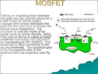
Mosfets • The metal- oxide- semiconductor- field- effect transistor is a type of transistor where the voltage determines the conductivity of the device. • The ability to change conductivity with the amount of applied voltage can be used for amplifying or switching electronic signals.. • MOSFETs are now even more common than BJTs (Bipolar junction transistors) in digital and analog circuits.
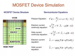
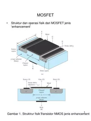
Working principle ofMOSFET • The working principle of MOSFET depends up on the MOS capacitor. • The MOS capacitor is the main part. • The semiconductor surface at below the oxide layer and between the drain and source terminal can be inverted from p-type to n-type by applying a positive or negative gate voltages respectively. • When we apply positive gate voltage the holes present beneath the oxide layer experience repulsive force and the holes are pushed downward with the substrate
Working principle ofMOSFET • The depletion region is populated by the bound negative charges, which are associated with the acceptoratoms. • The positive voltage also attracts electrons from the n+ source and drain regions in to the channel. • The electron reach channel is formed. Now, if a voltage is applied between the source and the drain, current flows freely between the source and drain gate voltage controls the electrons concentration thechannel. • Instead of positive if apply negative voltage a hole channel will be formed beneath the oxidelayer.
When current is applied a bridge of electrons is formed/ a ntype region which let the current pass through
TYPES OF MOSFET MOSFET • Enhancement MOSFET • N-channel E-MOSFET • P-channel E-MOSFET • Depletion MOSFET • N-channel D-MOSFET • P-channel D-MOSFET
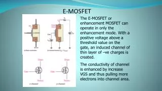
Enhancement Mode MOSFET • Enhancement Mode: • When there is no voltage on the gate terminal the device does not conduct. • More voltage applied on the gate terminal, the device has good conductivity. • Requires a Gate-Source voltage, (VGS) to switch the device “ON”. • Does not conduct at 0 volt, as there is no channel in this type to conduct.
Depletion Mode MOSFET • Depletion Mode: • When there is zero voltage on the gate terminal, the channel shows its maximum conductance. • As the voltage on the gate is negative or positive, then decreases the channel conductivity. • There are depletion–mode MOSFET devices, which are less commonly used than the standard enhancement–mode devices already described. These are MOSFET devices that are doped so that a channel exists even with a zero voltage from gate to source.
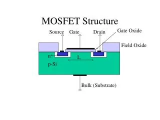
N and P channel of MOSFET • If the MOSFET is an n-channel or nMOSFET, then the source and drain are ‘n+’ regions and the body is a ‘p’ region. • If the MOSFET is a p-channel or pMOSFET, then the source and drain are ‘p+’ regions and the body is a ‘n’ region.
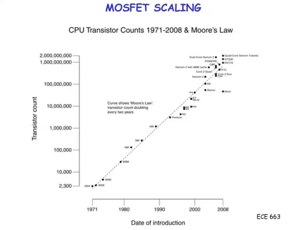
Advancements of theMOSFET • The explosion of digital technologies has pushed the advancement of MOSFET technologies faster than any other Si transistor. This has happened due to the MOSFET being the prime building block of CMOS digital logic circuits. • CMOS circuits are advantageous because they allow virtually no current to pass through and thus consume very little power.
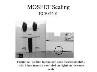
Limitations of theMOSFET • Overheating is very much a concern when considering today's integrated circuits contain millions of transistors in a relatively smallspace. • Recently, the small size of MOSFETs has created operational problems as producing such tiny transistors is an enormous challenge,
Mosfet applications • MOSFET used as a switch. • Auto intensity control of street lights using MOSFET. • LDR based power saver for intensity controlled street light. • SVPWM space vector pulse width modulation.
MOSFET USED AS A SWITCH. • In this circuit , N- MOSFET ia being used to switch the lamp for ON and OFF. • The positive voltage is applied at the gate of the MOSFET and the lamp is ON. • At the zero voltage level the device turns OFF. • If the resistance load of the lamp was to be replaced by an inductive load and connected to the relay of diode to protect the load.
AUTO INTENSITY CONTROLL OF STREET LIGHTS USING MOSFET. • It is to control the lights automatically on the highways using microprocessor by variants of the clock pulses. • MOSFET plays major role that is used to switch the lamps as per the requirement. • Here we can replace the the LEDs in place of HID lamps. • Which are connected to the processor with the help of the MOSFET.
LDR based power saver for intensity controlled street light. • n HID lamp intensity cannot be controlled according to the requirement. • So there is a need to switch to an alternative method of lighting system,using LEDs. • Its intensity cannot be controlled according to requirement during non-peak hours. • The microcontroller contains programmable instructions that controls the intensity of lights based on the PWM signals generated.
SPACE VECTOR PULSE WIDTH MODULATION. • The SPACE VECTOR PWM is a sophisticated technique for controlling AC motors by generating a fundamental sine wave that provides a pure voltage to the motor with lower total harmonic distortion. • In this system , DC supply is produced from the single phase AC after rectification. • It is fed to 3-phase inverter with 6 numbers of MOSFETS. • For each phase , a pair of MOSFET are used .