Download
1 / 18
180 likes | 304 Views
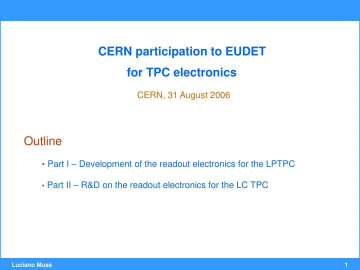
CERN participation to EUDET for TPC electronics CERN, 31 August 2006. Outline Part I – Development of the readout electronics for the LPTPC Part II – R&D on the readout electronics for the LC TPC. PART I Development of the readout electronics for the LPTPC.

E N D
CERN participation to EUDET for TPC electronics CERN, 31 August 2006 • Outline • Part I – Development of the readout electronics for the LPTPC • Part II – R&D on the readout electronics for the LC TPC
PART I Development of the readout electronics for the LPTPC
General requirements and strategy (1/2) Joachim Mnich (25.10.2005) • Readout electronics for the Large Prototype TPC (LPTPC) • modular with well defined interface for • various amplifcation technologies (GEM & µMegas) • different module geometries • easy to use and modern DAQ system • integrated pre-amps and digitization on TPC end flange • should be first step towards ILC TPC electronics • Two strategies pursued in EUDET • new TDC (Rostock) • ALTRO-based (Lund, CERN)
17 cm 19 cm ALICE TPC Front End Card Integrated charge amplification, digitization and signal preprocessing in the TPC end plate 128 channels
Readout & Control Backplane Readout and Control Backplane 25 Front End Cards • Readout Bus (BW = 200 MB /sec) • VME-like protocol + syncrhonous block transfer • Control Bus (BW = 3 Mbit / sec) • I2C interface + interrupt feature • point-to-point lines for remote power control of FECs
Readout Control Unit 3/3 SIU CARD ALICE TPC RCU (requires DDL + PCI RORC) Detector Data Link Ethernet interface TTC Interface DCS CARD Power Regulators
USB to FEC Interface Card (U2F) The U2F Card can read up to 16 FECs (2048 channels) U2F Card • U2F is functionally identical (readout and monitoring) to the RCU • ALICE Detector Data Link (DDL) and DCS Ethernet link replaced by USB link
SPI Card + ALICE TPC FEC Reading GEM and MICROMEGAS with the ALICE TPC FEC Signal Polarity Inverter (SPI) Card
An example: HARP FC + GEM R/O + SPI + FEC + U2F CERN – PS, November 2005
General requirements and strategy (2/2) • In the EUDET Collaboration Meeting at Nikhef (Jan 06), it was decided • For the LPTPC only the ALTRO based solution will be pursued • 1000 or 2000 channels according to the availability of ALTRO chips • system components and responsabilities • interface between TPC readout plane and FEE (Lund) • new shaping amplifer chip (CERN) • 40-MHz ALTRO (CERN) • Front End Card (PASA + ALTRO): • new design (based on CERN ALICE FEC) (Lund) • production and test (Lund) • U2F card (CERN) • System integration and test (Lund) • DAQ (Lund)
Status of CERN contribution • Participation to the definition of the interface between readout plane and FEE: several options are being studied and worked out in detail (small CERN contr.) • New shaping amplifier chip: well advanced (see second part of this present.) • 40-MHz ALTRO chip: about 150 chips have to be unsoldered from exsisting FECs (obsolete ALICE prototypes). This work is planned for Q1 2007. • U2F card (CERN): 4 new boards have been produced and tested • SPI cards: 2 new boards have been produced and tested • 2 complete readout system (SPI + FEC + U2F + Labview Software) have been prepared and transferred to Lund (April) and Aachen (June)
PART II R&D on readout electronics for the LC TPC General Purpose Charge Readout Chip
A general purpose charge readout chip number of channels: 32 or 64 programmable charge amplifier: sensitive to a charge in the range: ~102- ~107 electrons Input capacitance: 0.1pF to 10pF high-speed high-resolution A/D converter: sampling rate in the range 40MHz - 160MHz; programmable digital filter for noise reduction and signal interpolation; a signal processor for the extraction and compression of the signal information (charge and time of occurrence). Motivations & Specifications 2/2
Charge Readout Chip Block Diagram Anti-Aliasing Filter Anti-Aliasing Filter Anti-Aliasing Filter Signal Processor Signal Processor Signal Processor Data Compression Data Compression Data Compression Multi-Acq Memory Multi-Acq Memory Multi-Acq Memory Charge Amplifier Charge Amplifier Charge Amplifier ADC ADC ADC I N T E R F A C E Hit Finder • Maximize S/N • reduce quantization error • reduce signal bandwidth • Correct for crosstalk and common mode noise • Optimum pulse shaping for extraction of pulse features Feature Extaction Histogrammer 32 / 64 Channel
Milestone I (Q1 2007) ⇒ Programmable Charge Amplifier (prototype) 16 channel charge amplifier + anti-aliasing filter Milestone II (Q2 2007) ⇒ 10-bit multi-rate ADC (prototype) 4-channel 10-bit 40-MHz ADC. The circuit can be operated as a 4-channel 40-MHz ADC or single-channel 160-MHz ADC Milestone III (Q2 2008) ⇒ Charge Readout Chip (prototype) This circuit incorporates 32 (or 64) channels. Milestone IV (Q2 2009) ⇒ Charge Readout Chip (final version) Project Milestones
5 versions 7 standard channels Programmable Charge Amplifier Gerd Trampitsch INPUTS Production Engineering Data • 12- channel 4th order CSA • various architectures (classical folded cascode, novel rail-to-rail amplifier) • process: IBM CMOS 0.13 mm • area: 3 mm2 • 1.5 V single supply • Package: CQFP 144 • MPR samples (40): Apr ‘06 single channel OUTPUTS
Programmable Charge Amplifier • The CQFP 144 package has the same pin-count and similar pinout as the ALICE TPC PASA • In the near future the new chip will be tested on a ALICE TPC FEC Next Step • Milestone I (Q4 2006) ⇒ Programmable Charge Amplifier (prototype) • 16 channel charge amplifier + anti-aliasing filter • Programmable peaking time (50ns – 500ns) and gain • Submission (?? To be discussed with Sandro)
up Phase Detector Charge Pump down Ref. Clock (40 MHz) Vctrl Voltage Controlled Delay Line CLK CLK A A A A fa fa A fb 4-Channel 40-MHZ ADC B fb fc A A B B fc CLK fd 2-Channel 80-MHZ ADC A fd fa C fb C A C C fc A 1-Channel 160-MHZ ADC C fd D C D A D Multi-Channel Time-InterleavedA/D Converter Upgrade of ALTRO ADC A/D A/D A/D A/D A/D