Download
1 / 29
300 likes | 509 Views
Radiation tests of the TPC FEE CERN, 30 August 2004. Luciano Musa – CERN / PH - ED. Content System overview Radiation Levels at the TPC Radiation Facilities and Test Setup Characterization (TID and SEE) of the FEC components Custom (ALTRO and PASA)

E N D
Radiation tests of the TPC FEECERN, 30 August 2004 Luciano Musa – CERN / PH - ED • Content • System overview • Radiation Levels at the TPC • Radiation Facilities and Test Setup • Characterization (TID and SEE) of the FEC components • Custom (ALTRO and PASA) • COTS (LDO, VREF, AMPLIFIERS, TRANSCEIVERS, BUFFERS, CAP., etc.) • FPGA (ALTERA ACEX1K30) • Characterization of RCU see the talks of D. Röhrich and C. Soos
CUSTOM, COTS, FPGA PASSIVE COMPONENTS capacitors and resistors COTS, FPGA System Overview Each of the 36 TPC Sectors contains 6 Readout Partitions ON DETECTOR COUNTING ROOM FEC 128 ch 13 FEC 128 ch 2 RCU FEC 128 ch 1 Data Proc. and Memory DDL ( 200 MB/s ) Bus controller ( conf. & R/O ) DETECTOR DAQ int. (DDL-SIU) DCS ( 1 MB/s ) FEC 128 ch 12 BOARD Controller DCS int. (Ethernet) Local Monitor and Control TTC optical Link (Clock, L1 and L2 ) Trigger int. (TTC-RX) FEC 128 ch 2 FEC 128 ch 1 Overall TPC: 4356 Front End Card 216 RCUs
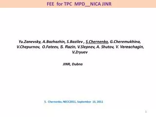
Radiation Levels at the TPC Simulation with 4 scoring regions TID @ TPCin 1.6 krad @ TPCout 0.22 krad Sum Flux with Ekin > 10MeV (cm-2 s-1) Layers 1 2 3 4 absorber side384 268 187 129 Non-absorber side245 149 112 81 Agreement with A, Morsch and B. Pastircak ALICE-INT-2002-28 Version 1.0 Georgios Tsiledakis, GSI
Radiation Facilities and Test Setup Test at UCL, Louvain-la-Neuve, Belgium Test (I) 2002 Scintillator Beam Type: 65 MeV protons Proton Flux: 1·108 , 5·108 p cm-2 s-1 100 krad in 30 min at this flux Attenuator Collimator DUT Test Bench 2 m Ethernet Line Labview Monitor Labview Server X Server with Labview
Regulator test on daughtercard Radiation Facilities and Test Setup Test Setup for ALTRO and LDO Test (I) 2002 PC Monitors status and errors Continuous current monitoring Analog card
Radiation Facilities and Test Setup Test (I) 2002 Collimator ALTRO chip Regulator Test Fixture
Radiation Facilities and Test Setup Test (I) 2002 EPROM (CMOS) FRONT END CARD Clock Driver 0.18 µm CMOS Analog Buffer CMOS PASA 0.35 µm CMOS
Radiation Facilities and Test Setup Test (I) 2002 GTL Transceivers (BiCMOS) FRONT END CARD Voltage Reference (Bipolar)
Radiation Facilities and Test Setup Test (I) 2002 Test Card used to monitor current Collimator
Radiation Facilities and Test Setup • Oslo Cyclotron • 25 and 28 MeV external proton beam • flux ~ 107 – 108 protons/s cm² • Beam profile: spot 1.5cm x 1.5cm Test (II) 2003 - 2004 • TSL (Uppsala) • 38 and 180 MeV external proton beam • flux ~ 107 – 108 protons/s cm² • Beam profile: • spot 3cm Test (III) 2004
Radiation Facilities and Test Setup Test Setup for COTS and FPGA Test (II) and TEST (III) 2003 - 2004
Tested Parts (1/2) Name Type Technology No. Parts TID (krad) ALTRO-16 ADC + DP CMOS 4 312 PASA Shaping/Amp CMOS 4 96 MIC39151 Volt. Reg. Bipolar 12 30 MIC29371 Volt. Reg. Bipolar 10 30 TC1173 Volt. Reg. Bipolar 6 40 LP3962/61 Volt. Reg. CMOS 3 30 TI757 Volt. Reg. CMOS 2 30 OPA4364 OpAmp Bipolar 5 30 AD8604 OpAmp CMOS 8 30 MAX4254 OpAmp CMOS 1 30 TC1265 Ref. Volt. CMOS 2 84 LM4140 Ref. Volt. Bipolar 10 30
Tested Parts (2/2) Name Type Technology No. Parts TID (krad) LM4040 / 41 Ref. Volt. Bipolar 10 30 LM385 Ref. Volt. Bipolar 10 30 STM-TS821 / 2 Ref. Volt. CMOS 4 30 GTL16612 Transceiver Bi-CMOS 8 48 MPC9109 Buffer CMOS 6 100 BAT54 Diode Bipolar 4 30 MMBT2222A BJT Bipolar 4 30 Electrolytic Cap Capacitors Tantalum 20 100 EPC1441 EPROM CMOS 10 ACEX1K30 FPGA CMOS 5 100 TOTAL NUMBER OF TESTED PARTS 146
Custom Components - ALTRO ALTRO Test Loop Start Register Check 2004 bits Current Check PM Check 163840 bits ADC Signal Check Reset ALTRO Write Pattern in Regs and Mem DM Check 655360 bits N Reset requested ALTRO Status Register Check Y
Custom Components - ALTRO ALTRO Test Program register errors analog current PM errors DM errors SEU errors and other standby digital current error counters protocol errors ADC spikes and SEU test phase power status
1 > 0 0 > 1 Custom Components - ALTRO Test Results bit-flip ratio Error Cross Section Memory Error Cross Section: 1.10·10-14 cm2 bit-1 Register Error Cross Section: 7.02·10-14 cm2 bit-1 Hamming Error Cross Section: 7.50·10-14 cm2 bit-1 Observations total current • Slightly more flips from 1 to 0 than from 0 to 1 • Digital current increases with dose (leakage increases) • Analog current stays the same • ADC bit flips very rare • Small spikes in analog part of ADC above 160 krad digital standby current
Custom Components - ALTRO Test Results Annealing • After 2 weeks at room temperature: 43 mA standby current (+13.5% over total) • After 3 months at room temperature: back to normal • At a low flux, annealing and damage may compensate All 4 irradiated chips continue to work today
Custom Components - ALTRO System Level Consequences For a sub-sector equipped with 200 ALTROS (1 RCU) Pedestal Memory Data Memory Hamming Machines Registers SEU per hour 0.023 0.36 1.43 0.0007 36 hours 168 minutes 42 minutes 58 days MTBF Worst-case figure Innermost Readout Partition @ absorber side
70 ADC COUNTS 0 Negative spikes in the baseline PASA Test Results Test Procedure • Monitoring of current consumption • Repetitive acquisition of output of 16 ch. • Monitoring of baseline value • Monitoring of gain • Automatic spike detection Test Results (TID = 96 krad) • No variations in current consumption • No variations in baseline level • No variations in gain • Negative spikes observed frequently (due to high flux)
COTS – Voltage Regulators MIC39151 died after 30 krad (switch-off still possible) MIC39151 beam stopped Switch-off still works 8 krad 25 krad 50 krad MIC39151 still usable for the TPC. Batch dispersion might be an issue
COTS – Reference Voltage Generators LM4040 (2.5V) (output stable within 0.3 %) Voltage (~21KRad/min) Time (hh:mm:ss) Voltage LM4041 (1.2V) (1% output variation @ 45Krad)
COTS – Operational Amplifier (Output stable ‘till ~140 Krad)
COTS – Bipolar Transistor (variations of 10 % in Vce-sat every ~140KRad)
COTS – Tantalum Capacitors 15uF / 10 V Voltage (up to 120KRad) Time (ms) Voltage Time (ms)
COTS – Other Results • GTL16612 max TID > 80 krad SEU cross section 1.15·10-12 cm2 bit-1 • MPC9109 max TID > 50 krad SEU cross section 1.3·10-12 cm-2 bit-1 • EPC1441 preserves configuration at TID > 20krad
COTS – FPGA (ACEX1K30) TID is not a problem at the TPC levels Two types of concern • Upsets in configuration SRAM cells • Single bit-flips in register elements (can be avoided by design) The ACEX1K30 offers no direct readout of configuration SRAM • Indirectly detection of configuration upset through the internal logic
10111 10000 01000 00011 00111 00000 00001 01111 00100 00101 00010 00110 11101 01001 11001 11011 10001 11000 SEU Protection • Finite State Machine (FSM) protected by Hamming encoding • Basic principle The arrival of X produces the transition from A to B Error 01100 X 1Bit-flip (SEU) Doble Bit-flip State A Returns to the associated state if there is no external signal producing a state transition Y State B State C The signal Y produces The transition form B to C, Arquitectura del Chip ALTRO
Serial Slow Control Network SCSN Serial Slow Control Network SCSN COTS – FPGA (ACEX1K30) Upset detection in ACEX devices A fixed pattern is shifted through and compared for setups when read out. Data out Data in FPGA 0000000 1000000 0100000 0010000 0001000 0000100 0000010 0010001 0000000 0000000 . . . 0000000 0000000 1000000 0100000 0010000 0001000 0000100 0000010 0000001 0000000 0000000 . . . 0000000
COTS – FPGA (ACEX1K30) Device Conf. Bits Cross Sec ACEX1K30 470 000 4•10-11 cm2 Error rate per run (4 hours) Error rate per run per device per system FEC 1.15*10-4 0.52 Detection of configuration loss by BIST FPGA reconfigured by on board EPROM