Download
1 / 27
350 likes | 762 Views
POWER AMPLIFIER. Bollen. Power amplifier Signals / definitions DC power supply AC signal power Efficiency Classes Class A type CE Class A type CC Push Pull. Cross over distortion Vbe Multiplier Thermal runaway Emitter resistors Temperature dependent Bias voltage

E N D
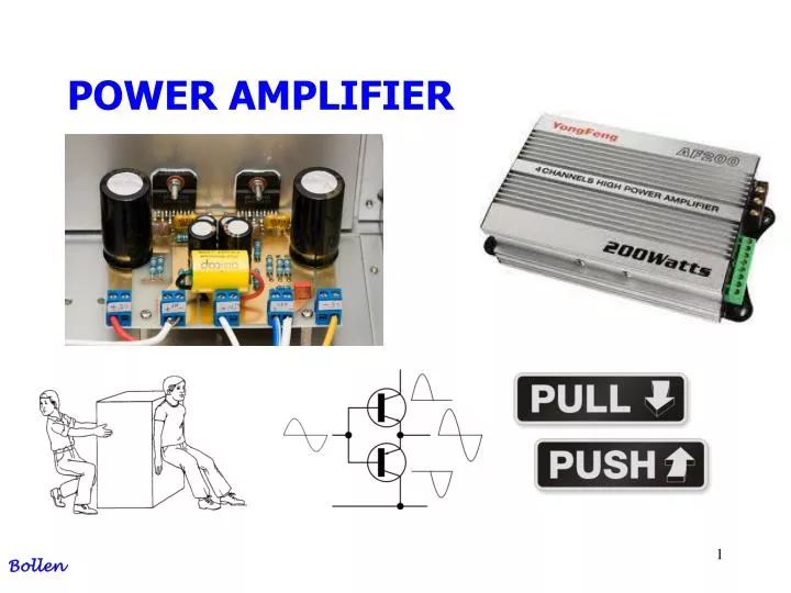
POWER AMPLIFIER Bollen
Power amplifier Signals / definitions DC power supply AC signal power Efficiency Classes Class A type CE Class A type CC Push Pull Cross over distortion Vbe Multiplier Thermal runaway Emitter resistors Temperature dependent Bias voltage Short circuit protection AGENDA Bollen
Power Amplifier Power amplifier = current amplifier Rloudspeaker = 8 Ohm, for 50 Watt >> I = 2,5 Ampere Power IN = DC power Power out = AC power Bollen
Signals / definitions 1/3 DC supply power DC-power = DC value for supply voltages, And Average for current waves Bollen
= efficiency / for definition see below Signals / definitions 3/3 efficiency So, POWER SUPPLY delivers DC or average power And the LOAD gets SIGNAL power (use root mean square value) Bollen
ɳ Bollen
Class-A Output device(s) conduct through 360 degrees of input cycle (never switch off) - A single output device is possible. The device conducts for the entire waveform Class-B Output devices conduct for 180 degrees (1/2 of input cycle) - for audio, two output devices in "push-pull" must be used Class-AB Halfway (or partway) between the above two examples (181 to 200 degrees typical) - also requires push-pull operation for audio. Classes Bollen
Class-C Output device(s) conduct for less than 180 degrees (100 to 150 degrees typical) - Radio Frequencies only - cannot be used for audio! This is the sound heard when one of the output devices goes open circuit in an audio amp! Class-D Quasi-digital amplification. Uses pulse-width-modulation of a high frequency (square wave) carrier to reproduce the audio signal. Classes Bollen
The configuration is a common emitter The load / loudspeaker is in the collector If there is no signal there is a quecient current to adjust Vc = ½ Vcc for symmetrical use of voltage range If there is no signal, the power supply should deliver power to the circuit The efficiency is very low The lost power is just dissipation: heating of components: so you need to cool for high power Class A type CE Bollen
Vcc = 40 Volt Rload = 8 Ohm Quesientpoint Uc = 20 volt I bias = 2,5 A I signal max = 2,5 A Class A Bollen
The configuration is a common collector The load / loudspeaker is connected to the emitter If there is no signal there is a quecient current to adjust Ve = ½ Vcc for symmetrical use of voltage range If there is no signal, the power supply should deliver power to the circuit The efficiency is very low The lost power is just dissipation: heating of components: so you need to cool for high power Class A type CC Bollen
Vcc = 40 Volt Rload = 8 Ohm Quesientpoint Uc = 20 volt Isignal max = 2,5 Ampere Class A Bollen
If you need water; open Q1 If you deliver water; Open Q2 Q1 and Q2 never opens at the same time Push Pull idea Bollen
Here the BJT are complementary (NPN and PNP) Each device amplify the opposite halves of the input signal At the output you get the total signal. excellent efficiency But small mismatch between the two halves of the signal Push Pull with transistors Bollen
Vcc = +20 Volt Vee = -20 Volt Rload = 8 Ohm Uin = 0 Volt Uout = 0 Volt So no bias current Vcc Push Pull in realisation Vee Bollen
Vcc Push Pull in realisation Vee Bollen
Dead zone = 1,4 Volt Cross-over distortion Bollen
Eliminating Cross-OverDistortion Shift NPN 0,7 Volt to left Shift PNP 0,7 Volt to right Bollen
Eliminating Cross-OverDistortion Shift 1,4 Volt Or Shift 2,8 Volt Or Something else … Bollen
Base current is negligible, so: VBE Vbe multiplier Inverse voltage divider !!! Bollen
Vbe multiplier Bollen
Fit a bigger heatsink. Use series emitter-resistors. Use a temperature dependent bias voltage. The latter two are preferred methods. Both introducenegative feedback. Thermal runaway Bollen
By symmetry: Emitter resisters So, if IC rises, VBE falls and IC is reduced. Note RE should be small compared with RL to minimise power wasted. Bollen
If junction temperature rises but IC stays the same, VBE must fall causing Vbias to fall also. Negative thermal feedback achieved if the transistor is in close contact with the output devices. Especially suitable for integrated circuits where close thermal contact is guaranteed. Temperaturedependent bias voltage Bollen
Current limitation Rx is a current measuring resistor If URx> 0,7 the T1 switches ON Then output current in limited !! Short circuit protection T1 Rx Bollen