Download
1 / 24
270 likes | 532 Views
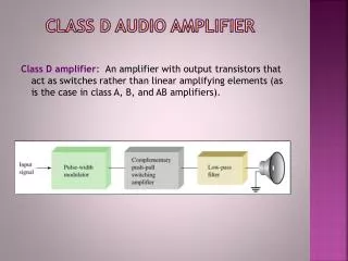
Audio Power Amplifier Detailed Design. By: Brian Felsmann. Audio Power Amplifier Detailed Design. Design Issues: Thermal Protection Circuits Maximum Power Dissipation Determining the Correct Heat Sink Voltage Gain Frequency Response Total Harmonic Distortion + Noise (THD + N)

E N D
Audio Power AmplifierDetailed Design By: Brian Felsmann
Audio Power AmplifierDetailed Design • Design Issues: • Thermal Protection Circuits • Maximum Power Dissipation • Determining the Correct Heat Sink • Voltage Gain • Frequency Response • Total Harmonic Distortion + Noise (THD + N) • Common Mode Rejection Ratio (CMRR) • Signal-to-Noise Ratio (SNR) • Over Voltage / Under Voltage Protection
Audio Power AmplifierDetailed Design • Thermal Protection Circuits (on LM4780) Protection to prevent long-term thermal stress When die temperature exceeds 150°C, the LM4780 shuts down until temperature falls below 145°C, then amp restarts Helps prevent thermal cycling Improves reliability Still need an adequate heat sink to prevent IC from approaching 150°C
Audio Power AmplifierDetailed Design • Maximum Power Dissipation Calculation • Power dissipation is the power that is converted to heat within the amplifier • Important parameter used to determine heat sinking requirements and output power • Pi + Ps = Po + Pd • Where: Pi = input signal power, • Ps = DC supply power, • Po = output signal power, and • Pd = dissipated power • Pd should be minimized so Po is maximized
Audio Power AmplifierDetailed Design • Maximum Power Dissipation Calculation • Determines size of heat sink • For Parallel Amplifier Configuration the equivalent impedance at the load is: • RL(parallel) = RL(total) * Number of Amps on IC • RL(parallel) = 8 ohms * 2 amps on IC = 16 ohms • Pdmax = (Vcc^2)/(2π^2*RL(parallel)) • Pdmax = (70V^2)/(2π^2*16 ohms) = 15.51 W • Pdmax = 2 * 15.51W = 31.02 W for both amps on IC
Audio Power AmplifierDetailed Design • Determining the Correct Heat Sink • Chosen to keep the die temperature of the amplifier IC below 150°C to prevent the thermal protection circuits to be activated under normal circumstances • Need to choose the heat sink with the lowest cost and smallest size for its thermal resistance
Audio Power AmplifierDetailed Design • Determining the Correct Heat Sink (con’t) • Convection heat flow or power dissipation is analogous to current flow • Thermal resistance is analogous to resistance • Temperature drops are analogous to voltage drops
Audio Power AmplifierDetailed Design • Determining the Correct Heat Sink (con’t) • Thermal resistance from die to outside air • θJA = θJC + θCS + θSA, where: θJC = thermal resistance (junction to case) θCS = thermal resistance (case to sink) θSA = thermal resistance (sink to air)
Audio Power AmplifierDetailed Design • Determining the Correct Heat Sink (con’t) • For the audio amplifier IC chosen, LM4780: θJC = 0.8°C/W θCS = 0.2°C/W and θJA = 30°C/W (max)
Audio Power AmplifierDetailed Design • Determining the Correct Heat Sink (con’t) • Using these analogies, power dissipation can be calculated, • Pdmax = (TJmax – TAmb)/θJA • TJmax = max junction (die) temp allowed for the LM4780 this is 150ºC • TAmb = ambient temperature
Audio Power AmplifierDetailed Design • Determining the Correct Heat Sink (con’t) • Finally, to calculate the sink to ambient thermal resistance, θSA, the equation for power dissipation can be used, • θSA = [(TJmax - TAmb)-PDmax(θJC+θCS)]/Pdmax • θSA = [(150°C - 50°C)-31.03(0.8+0.2)]/31.03 = 2.22 • θSA = 2.22°C/W for worst case ambient temp of 50ºC
Audio Power AmplifierDetailed Design • Voltage Gain Calculation • Non-inverting configuration: • Av = Rf/Rin + 1 = 20k/1k + 1 = 21 • Av (dB) = 20log(21) = 26.4 dB • This is the voltage gain for one amplifier on IC
Audio Power AmplifierDetailed Design • Under-Voltage Protection of LM4780 allows power supplies and voltage across capacitors to reach full values before amp turned on to prevent DC output spikes • Over-Voltage Protection of LM4780 limits the output current while providing voltage clamping
Audio Power AmplifierDetailed Design • Power Supply Bypassing • LM4780 has excellent power supply rejection • To improve performance, bypass capacitors are needed on power supply • Eliminates possible oscillations
Audio Power AmplifierDetailed Design • Parallel Amplifier Configuration • LM4780 has two op-amps internally, so load can be driven with both op-amps on IC for higher output power • Design both amplifiers to have close to identical gain • Connect inputs in parallel • Connect outputs in parallel through a small R • Ideally each amplifier shares output current equally
Audio Power AmplifierDetailed Design • Electrical Characteristics for the LM4780 Audio Power Amplifier • Total Harmonic Distortion + Noise (THD+N) = 0.03% (typical) • Conditions: Pout = 30 W, f = 20Hz – 20kHz, Av = 26 dB, Po = 30 W and RL = 8Ω
Audio Power AmplifierDetailed Design • Electrical Characteristics for the LM4780 Audio Power Amplifier Output Power (Po) = 60 W (typical) Conditions: f = 1kHz, f = 20 kHz, THD + N = 0.5%, Vcc = 35V and RL = 8Ω
Audio Power AmplifierDetailed Design • Electrical Characteristics for the LM4780 Audio Power Amplifier Common Mode Rejection Ratio (CMRR) = 110 dB (typical) and 85 dB (min) Conditions: Vcc = 35V and Vcm = 20V to –20V
Audio Power AmplifierDetailed Design • Electrical Characteristics for the LM4780 Audio Power Amplifier Signal-to-Noise Ratio (SNR) = 114 dB (typical) Conditions: Po = 50W rms
Audio Power AmplifierDetailed Design • Functions of Components: • R1: sets input terminals DC bias & HPF with C1 • R2 (R3): limits current into non-inverting terminal • R4 (R5): sets gain along with R6 (R7) • R8 (R9): sets high frequency pole to prevent oscillations • R10 (R11): limits current to output load • C1: input coupling capacitor • C2 (C3): HPF with R4 (R5) • C4, C5, C6 & C9, C10, C11: power supply filtering capacitors • C7 (C8): sets high frequency pole to prevent oscillations
Audio Power AmplifierDetailed Design • Offset Error Contribution: • Error Voltage due to Vio: Verr = Vio(1+Rf/Rp) Verr = 10mV(1+20k/1k) = 210 mV
Audio Power AmplifierDetailed Design • Gain Error: (5% tolerance resistors) • Av(nom) = 1 + Rf/Rp = 1 + 20k/1k = 21 • Resistor Tolerances: Assume Rf = Rf + 5% and Rp = Rp – 5%, then • If Rf = 21k and Rp = 0.95k, then • Av = 1 + 21k/0.95k = 23.1 • Gain Error = Av(nom) – Av = 21 – 23.1 = 2.1
Audio Power AmplifierDetailed Design For the parallel amplifier configuration, the gain of each amplifier must be matched, so only 1% tolerance resistors can be used • Gain Error (1% tolerance resistors) • Resistor Tolerances: Assume Rf = Rf + 1% and Rp = Rp – 1% then • Rf = 20.2k and Rp = 0.99k • The Av = 1 + Rf/Rp = 1 + 20.2k/0.99k = 21.4 • Gain Error = Av(nom) – Av = 21 – 21.4 = 0.4