Download
1 / 49
490 likes | 607 Views
Local Structures of Electron Temperature and Electrostatic Potential during ST Merging Startup. * Boxin Gao, Akihiro Kuwahata Inomoto Lab The University of Tokyo School of Engineering Department of Electrical Engineering and Information Systems . Outline. Introduction

E N D
Local Structures of Electron Temperature and Electrostatic Potential during ST Merging Startup *Boxin Gao, Akihiro Kuwahata InomotoLab The University of Tokyo School of Engineering Department of Electrical Engineering and Information Systems
Outline • Introduction • Plasma mergingtechnique for economical fusion reactor • Magnetic reconnection • Research purpose • Experimental device and measurement • Plasma merging device • Measurement methods • Multi-channel Langmuir probes array • Experiment result • 2D Electron Temperature • 2D Electrostatic Potential • Summary and Future work
Plasma MergingStartup • Spherical Tokomak (ST) is one of the promising concepts for magnetically confined fusion reactor because of its high beta and economic efficiency. • To establish center-solenoid-free startup, various schemes such as RF, helicity injection and plasma merging, have been proposed. Fig: Plasma merging startup Magneticreconnection Magnetic reconnection is considered as the main factor of plasma heating.
Magnetic Reconnection • Reconfigure magnetic field to a lower-energy state • Release magnetic energy to surroundings • Heat plasma • Produce plasma flows Magnetic field lines of opposite polarity are reconnected each other. Fig: Magnetic reconnection in space Fig: Magnetic reconnection
Research Purpose Magnetic reconnection operates in company with high guide field during in ST merging start-up • Experiment observation on ion heating at reconnection outflow through fast shock[1] • Simulation on electron acceleration by parallel electric field at X point in high guide field[2] • Examine the electron heating mechanism in ST merging start-up. • Investigate the electron acceleration by in-plane electric field in high guide field.
Plasma merging device Basic parameter R ~ 0.45 m Bt ~ 0.10 T Br~ 0.05 T Ti ~ 20eVTe~ 5-20eV ne ~ 1x10¹⁹m-3 li-skin~ 4cm ri-larmor~ 2 mm Fig: Plasma merging device
Plasma merging process • Create 2 torus plasma • Reverse PF current • make them emerge with each other Fig: TS-4 device Reconnection point Fig: Plasma merging process
Measurement Method End View • Quadruple probe • Include a triple probe which acquires Te and ne • Acquire plasma floating potential tungsten plasma Glass tube 2mm 1mm P2 P3 P1 P4 5mm / 10mm Chamber One channel configuration : Vf Triple Probe Fig: quadruple probe Fig: 5-channel quadruple probe
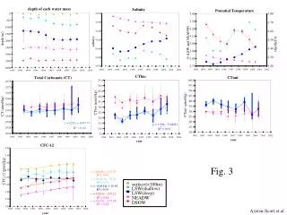
Electron Temperature Reconnection rate and magnetic flux t1 t2 t3 t4 Electron temperature: • Electron heating both in current sheet and in outflow. • Maximum electron temperature at peak of reconnection rate. • Symmetric outflow electron heating at low reconnection ratebut the asymmetric heating at the peak of reconnection rate.
Electrostatic Potential Reconnection rate t2 t1 t4 t3 Floating potential and magnetic flux: • Quadruple distribution is observed at the peak of reconnection rate. • Great gradient of floating potential at the peak of reconnection rate.
Ep Distribution • High in-plane electrostatic filed occurred during reconnection.
ExB Drift Motion • Strong in-plane electric field is induced to keep the ExB drift motion. • Particles’ motion will be strongly affected by this in-plane electric field.
Summary & Future work • 2D profile of temperature was measured during magnetic reconnection with high guide field. • 2D profile of the in-plane electric field was measured during magnetic reconnection with high guide field. • Increase the 2D profile resolution of and . • Find the parameter dependence among ,and
Reference [1] Y. Ono and H. Tanabe: “Ion and Electron Heating Characteristics of Magnetic Reconnection in Tokamak Plasma Merging Experiments”, Plasma Physics and Controlled Fusion, Vol.54, No.12, 124039 (2012) [2] G. Lapenta and S. Markidis: “Scales of Guide Field Reconnection at the Hydrogen Mass Ratio”, Physics of Plasmas, Vol.17, No.8, 082106 (2010) [3] P. L. Pritchett , Collisionless magnetic reconnection in a three-dimensional open system, Journal of geophysical research, Vol.106, Nov 1, 2001 [4] J. F. Drake, M. A. Shay, The Hall fields and fast magnetic reconnection, Physics of plasmas, 2008 [5] S. Chen, T. Sekiguchi, Instantaneous direct-display system of plasma parameters by means of triple probe, Journal of applied physics, Vol.36, No.8, Aug, 1965 [6] J. Yoo, M. Yamada, Observation of ion acceleration and heating during collisionless magnetic reconnection in a laboratory plasma, Vol. 110, 215007, 2013 [7] J. Egedal, W. Fox, Laboratory observations of spontaneous magnetic reconnection, Physical review letters, Vol. 98, 015003, 2007 [8] J. P. Eastwood, M. A.Shay, Asymmetry of the Ion Diffusion Region Hall Electric and Magnetic Fields during Guide Field Reconnection: Observations and Comparison with Simulations, Physical review letters, Vol. 104, May 21, 2010 [9] T. D. Tharp, M. Yamada, Study of the effects of guide field on Hall reconnection, Physics of Plasmas, Vol. 20, 055705, 2013
Reconnection in guide field • Bt (out-of-plane) appears as guide field drift motion : =0 Out-of-plane E component only no guide field: ( Bt = 0 ) =0 The same 1st term 2nd term under guide field: In-plane E component Out-of-plane E component
ne G. Lapenta and S. Markidis, Physics of Plasmas, Vol.17, No.8, 082106 (2010)
Vp [6]
ne • After probe compensation:
Nuclear fusion • Next generation of electric power plant • Less pollution • Low risk and radiation • Powerful and stable supply • The international tokamak facility called ITER is now under construction • Large amounts of super-conducting coil to generate high toroidal magnetic field • Largest portion of construction cost Low cost is essential for practical application of fusion power Fig: ITER 2020 ~
High β plasma • Total Output fusion power is in proportion to value • b: ratio of plasma thermal pressure to magnetic pressure High beta plasma is expected The smaller Aspect ratio the higher beta • b value is limited in tokamak plasma • Aspect ratio A = R0/a by Troyon’s law
Spherical tokamak(ST) • A promising candidate for fusion reactor core plasma • High b is achievable (up to 50%) [1] • Better confinement property • Compact, low cost in construction and operation
Problem in ST Problem in ST : Little space for Centre Solenoid (CS) coil Plasma start-up method without CS coil is investigated Fig: CS coils used in tokamak
CS-less Plasma start-up method • Waves injection startup • Electron cyclotronwaves injection • Radio-frequency waves injection • Plasma merging startup [2] • Compact and economical • Achieve high b plasma • Heat plasma through magnetic reconnection process • Form a stable ST configuration efficiently • Unnecessary of instability prevention process • Less usage of external heating instrument(such as NBI,RF…) Magneticreconnection Fig: Plasma merging startup
2-fluid Hall Effect Fig: Two-fluid dynamics in the reconnection layer Fig: Hall reconnection simulation [9]. • Difference movement between ion fluid and electron fluid • Ion : big mass; less magnetized; big Larmor radius • electron : few mass; strongly magnetized; small Larmor radius • Magnetic energy => kinetic energy and thermal energy • Ion and electron outflow are observed [3] • Symmetry quad-pole distribution Fig: Hall reconnection in experiment [9].
Hall Effect in guide field Fig: Hall reconnection configuration in guide field • Guide field always existed in ST • Asymmetry quad-pole distribution • Recent observation of hall effect in guide field • Magnetic field distribution [9] • Magnetic fluctuation [10] • Ion temperature distribution [11] • Undefined • Electron temperature distribution • Electrostatics potential distribution • Electrostatics fluctuation Fig: Hall reconnection simulation [9]. Fig: Hall reconnection in experiment [9].
Research purpose • Invest the mechanism of energy transformation in collisionless magnetic reconnection with guide field • Find how electron is heated in reconnection region • Measure electron temperature distribution • Find whether electrostatic potential contribute to ion energy • Acquire electrostatic potential distribution • Find whether electrostatic waves influence on plasma heating • Obtain electrostatic fluctuation
Measurement method • Triple probe • Low cost and easy alignment • Excellent in spatial resolutions • No voltage, frequency sweeps/switch • Acquire plasma parameter Te and ne … simultaneously P1 P2 P3 Probes plasma I Vd2 Vd3 A powerful diagnostic tool even for rapidly changing time-dependent plasma Fig: Triple probe
Electron temperature and density Plasma electron temperature () : plasma ; P1 P2 P3 [5] Probes I Plasma electron density ( ) : Measured Vd2 Vd3 [5] (fixed) Fig: Triple probe
Quadruple probe array One channel configuration : End View tungsten Glass tube 2mm 1mm 5mm / 10mm Fig: 5-channel quadruple probe 1 Probe array configuration: Probe End View 20mm Fig: End view of 5-channel probe 1 Fig: 5-channel quadruple probe 2
3D Fluctuation probe Probe configuration : 0.5mm Side View : 2mm End View : 1mm 2.5mm 0.5mm 2mm 4mm 1mm Tungsten Fig: 3D fluctuation probe Ceramic
Alignment 5 channel probe 1 5 channel probe 2 Fig: Plasma merging device
Vf distributionof Hydrogen • Quad-pole distribution of floating potential was observed • A typical evidence of hall effect in magnetic reconnection • About 10[eV] ion kinetic energy transformed from electrostatic energy are confirmed
ExBDrift Motion of Electron drift motion : --------------------------- [プラズマ物理入門 P20] Vfはt方向に一様(軸対象性)
ExB Drift Motion During reconnection After reconnection Inflow (Out-plane component) (In-plane component) (total) Outflow • ExB Drift motion component by in-plane electric field is dominate over that by out-plane electric field .
ExB Drift Motion (1st term ) • The Inflow and outflow is much similar to those in Sweet-Parker model.
ExB Drift Motion (2nd term) • ExB drift motion caused by electrostatic field comes significant during reconnection period • Electrostatic field greatly increases the speed of inflow and outflow in magnetic reconnection area
ExB Drift Motion • ExB drift motion of electron in guide field is dominant by electrostatic field
ExB Drift Motion (1st term) • Vp (Et only) --> (0.0000 1.0427) km/s • Vp(Ep only) --> (0.0191 35.6529) km/s • Vp (Et with Ep) --> (0.0331 35.4518) km/s • Et (Et only) --> (-137.7242 56.7613) V/m • Ez (Ep only) --> (-1129.2 1755.9) V/m • Er(Et with Ep) --> (-1051.5 1146.9) V/m
Electron Temperature Te in mid-plane (z=0) : During reconnection After reconnection • Electron heating at outflow region is observed
Electron Density ne in mid-plane (z=0) : Before reconnection During reconnection After reconnection • Electron density is greatly affected by plasma confinement in stead of magnetic reconnection • Electron density is not obviously changed between outflow region