Download
1 / 7
70 likes | 158 Views
Representing Systems II. Seventh Meeting. Class - Associations. Relationships between objects Example: “on top of” windows is A “on top of” window B “part of” a drop-down menu ‘is part of’ a window. Other names: aggregation or containment. Class - Multiplicity.

E N D
Representing Systems II Seventh Meeting
Class - Associations • Relationships between objects • Example: • “on top of” • windows is A “on top of” window B • “part of” • a drop-down menu ‘is part of’ a window. • Other names: aggregation or containment
Class - Multiplicity • How many instances of each of the classes are involved in the relationship. • one-to-one relationship • One Status bar “is part of” One Window • one-to-many relationship • Many Drop-down menus “is part of” One Window • many-to-many relationship • Many Windows ‘is on top of’ Many Windows
Building Object Oriented Model Building object model • Identify the classes of objects which make up the system. • Define the relationships between the classes. • Specify the attributes for the classes. Defining system behavior (Dynamic model) • Identify the messages which need to pass between the objects. • Assign operations to the different classes. Reference model • Defines a collection of standard object classes which can each perform certain well-defined tasks.
Event Flow Diagram • Specify the flow of messages between objects in response to particular events. • This clarifies which objects are involved in a specific scenario and the part played by each object.
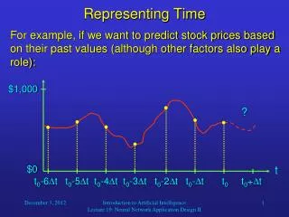
Specification and Description Language • SDL is used to represent real-time systems • SDL systems communicate by passing discrete messages between each other. • Represent distributed parallel systems, • system can perform independent actions simultaneously or concurrently. 33242539242829292024332 Parallel System
SDL Process • SDL Uses processes to describe the behavior of a system. A process • Receives signals while in a ‘state‘ • Uses values stored in data variables to influence its behavior. • Stores input signals in a FIFO queue • Can be defined to represent non-deterministic behavior. • Process Diagram • A process is represented diagrammatically • The structure of a system is described using system diagrams and block diagrams Add Heat Add Heat