Download

1 / 18
180 likes | 188 Views
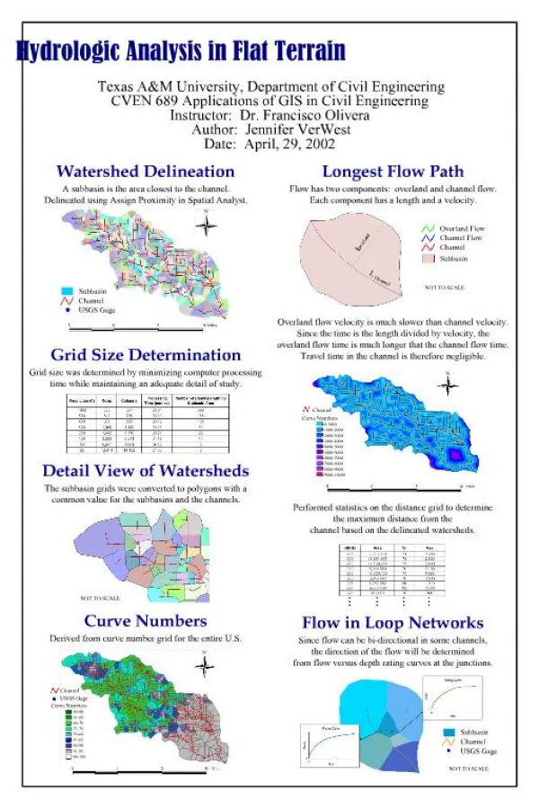
Lower Platte Missouri Tributaries Model Hydrologic Connection Analysis. Lower Platte Basin Tech Committee Meeting March 4, 2019. Philip Paitz Water Planning IWM Analyst. Outline. Lower Platte Missouri Tributaries (LPMT) Model Construction Timeline

E N D
Lower Platte Missouri Tributaries Model Hydrologic Connection Analysis Lower Platte Basin Tech Committee Meeting March 4, 2019 Philip Paitz Water Planning IWM Analyst
Outline • Lower Platte Missouri Tributaries (LPMT) Model Construction Timeline • LPMT Model Construction Domain and Boundaries • Cycle Well Analysis • Cycle Well Zones • Results – All Zones, Missouri Tributary Zones, and a Single Zone
Why Was the LPMT Model Constructed? • Provide a regional numerical groundwater model to aid in the study of the impact of pumping on streams in the area • Before the development of the LPMT model there was no regional model encompassing the eastern region of Nebraska. The LPMT model covers the northern and central part of that region • Region contains complex hydrogeologic features which range from the High Plains Aquifer in the western side, to alluvial aquifers near the major streams, and local perched and semi-perched aquifers in regions containing glacial till
LPMT Model Construction Timeline • Three HDR reports from 2012, 2013, and 2014 provided the basis for the development of the model • Initial model work started in July of 2014. Model development was contracted out to HDR • First version of the model was finished late 2016 and was reviewed by Olsson Associates. Revisions requested included separating the evapotranspiration from the watershed model to an EVT package, incorporating pilot points, and modify the zonation constraints • Final model incorporating revisions from the review was finished December of 2018
LPMT Model Construction Domain and Boundaries • Layers • Model contains two layers where Layer 1 represents the principle aquifer and Layer 2 represents various bedrock aquifer units • Grid • Consists of 350 Rows and 282 Columns of ½ Mile by ½ Mile cells • 64,347 active cells in Layer 1 • 69,168 active cells in Layer 2 • Stress Periods – January 1960 through December 2013 • 1 Steady State, 26 Transient Annual, 336 Transient Monthly • Packages • Well, Recharge, Stream Flow Routing, River, and Evapotranspiration
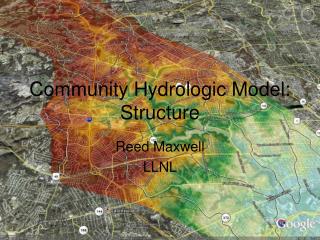
Cycle Well Analysis Natural Condition Capture Induced Infiltration
Cycle Well Analysis • In order to calculate Stream Depletion Factors a cycle of pumping of a known, fixed quantity for every stress period by a fictional well is needed • This process is repeated for every cell in a model’s active domain is the cumulative stream leakage after the new well is the cumulative stream leakage of the baseline is the total pumping from the new well
Cycle Well Analysis is the cumulative stream leakage after the new well is the cumulative stream leakage of the baseline is the total pumping from the new well
LPMT Cycle Well Setup • Hydrologic connectivity determined by running a fifty year simulation • LPMT cycle well analysis consists of original models 336 transient monthly stress periods plus the last 132 repeated twice • Original 336 transient periods – Jan 1986 to Dec 2013 • Repeated last 127 periods twice - Jan 2002 to Dec 2013 • Total of 600 stress period representing fifty years • All model packages were modified to represent the stress period changes
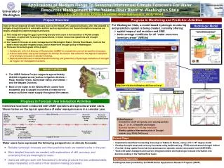
LPMT Cycle Well Zones • Zones were created to aid in the analysis of hydrologically connected areas • The zones are based off of HUC 10 Watershed boundaries and are the same for both layers • Missouri, Blue, Loup, and Platte Tributaries were grouped • Bazille and Elkhorn watersheds without stream cells were grouped • Total of fifty nine zones
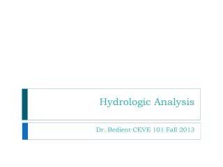
LPMT Cycle Well Results 1 All Zones
LPMT Cycle Well Results 2 Missouri Tributary Zones
LPMT Cycle Well Results 3 Single Tributary Zone
What’s Left to Do? • Finish post-processing the cycle well results • QAQC the process, post-processing, and results • Export results to shapefiles and create final csv files for each zone • Finalize documentation and write metadata for shapefiles • Distribute results to public • Also ahead with the NRD’s help • Examine and incorporate AEM data into the LPMT Model • Develop local sub-models
Summary • LPMT Model was constructed to aid in the study of impact to streams within the region with an emphasis on hydrologic connectivity • Cycle well analysis was conducted using the LPMT Model expanded to fifty years • Zones allow for hydrologic connectivity to analyzed at watershed level • Post-processing and QAQC need to be completed
Philip Paitz Water Planning IWM Analyst philip.paitz@nebraska.gov