Download
1 / 46
500 likes | 731 Views
Bio-Inspired wind energy harvester. Advisors: Dr. Manish Paliwal and Dr. Lisa Grega Kevin Hynes David Talarico. Energy Demand. At the current time, we have used somewhere around half of the earth’s natural supply of fossil fuels

E N D
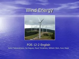
Bio-Inspired wind energy harvester Advisors: Dr. Manish Paliwal and Dr. Lisa Grega Kevin Hynes David Talarico
Energy Demand • At the current time, we have used somewhere around half of the earth’s natural supply of fossil fuels • How will we continue to supply society with the energy it needs to function?
Energy Demand • 1 in 4 people in the world live without electricity • This energy poverty is the biggest limitation to improving living conditions • Need for a cheap open source design
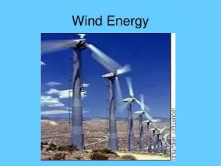
Modern Wind PowerThe 3 rotor horizontal-axis wind turbine • Blades spin a central shaft • Shaft runs to a gearbox • Gearbox steps up shaft speed to 60Hz in generator
Problem Statement • Use linear, oscillatory movement to improve wind energy capture technology in one or more of the following categories: • Overall efficiency • Energy produced per dollar input • Energy produced per unit area of land used • Design a system that exploits rather than mitigates vortex energy • Make design as simple and modular as possible • Lower shipping and maintenance costs • Opening the door to ‘open source’ use • Use vibrational modeling to widen range of resonant behavior
Vortex Shedding Characteristics • Forces exerted on cylinder only from vortex shedding • Forces exerted on airfoil to due pressure differential (lift) as well as vortex formation and shedding Drucker E G , Lauder G V Integr. Comp. Biol. 2002;42:243-257
Vortex Shedding Characteristics • ‘Synchronization’ of a vibrational system occurs where driving frequency approaches natural frequency • Mass ratio defined as m* = mass of system/mass of displaced fluid • Plot of oscillatory frequency vs. • This occurs over a large range of flow speeds if the mass ratio is very low • Low mass ratio allows the system to respond more quickly
Vortex Shedding Characteristics • ‘Delayed Stall’ • Proves concept that a leading edge vortex (LEV) provides an additional lift force during the time that it remains in contact with the wing E. Swanton, B. Vanier, and K. Mohseni, Leading Edge Vortex Stability in a Flapping Model Hummingbird Wing, 38th Fluid Dynamics Conference and Exhibit, AIAA paper 2008-3718, Seattle, OR, June 23-26, 2008.
Proposed System • Pitching- rotational movement of wing • Plunging- translational movement of wing • Coupling these two motions will allow the design of a system that can extract flow energy through lift and vortex formation Kinsey and Dumas 2008
Design Parameters • Plunge Amplitude (Ho) • Pitch Amplitude (θo) • Effective angle of attack (α) • Chord Length (c) • Airfoil Thickness • Pitching Center • Frequency of Oscillation • Flow Speed (U∞) • Motion characteristics • Vibration constants
Design Concepts • Reduced frequency = f* = fc/U∞ • Thickness has a negligible effect on efficiency • Our Design: More flexibility on selection of airfoil design
Design Concepts • Optimal pitching center location found to be 1/3 • Efficiency increases with Reynolds number • Our Design Re~30,000
Design Concepts • Sine curve is position vs. time • Slope is velocity • Resultant of lift and drag resolved into X and Y components • Power vs. Propulsion • Effective angle of attack • Y-component in phase with velocity • Quasi-steady assumption
Design Concepts • Propulsion = High energy wake • Power extraction = Low Energy wake • Our Design: Must keep Y-component of force in phase with velocity
Design Concepts “Energy Harvesting through Flow-Induced Oscillations of a Foil” • A ‘Leading Edge Vortex’ (LEV) is formed at the leading edge of an airfoil that is about to undergo flow separation • LEV energy can be recovered at the trailing edge – depends on LEV-foil interaction and timing • This occurs over a large range of flow speeds at a low mass ratio • Unsteady phenomenon
Design Concepts • Leading Edge Vortex Synchronization (LEVS) dependent on maximum pitching amplitude and reduced frequency • Optimal pitching amplitude ~ 75° • Optimal reduced frequency ~ 0.15 • Our Design: Use as baseline
Design Concepts • What is the most efficient form of movement? - Power extraction dominated by vertical force in phase with vertical velocity - Square wave ensures that the movement of the wing spends the most time in the power stroke, highlighted below, where the Y-component of force and velocity are both at their maximum - ‘Power Strokes’ ended by rapid pitching of airfoil and change in vertical direction
Design Concepts Sinusoidal vs. Non-Sinusoidal (Square Wave) Oscillation “Extracting Power from the Jet Stream: Pushing the Performance of Flapping Wing Technology” Platzer et. al.
Summary • Mass ratio of wing must be very low • Thickness has a negligible effect on efficiency • Optimal pitching center location found to be 1/3 • Efficiency increases with increasing Reynolds number • Pitching amplitude and reduced frequency –extremely important parameters • Strive for θ0 ≈ 75° and f*=0.15 for highest efficiency • Optimal vertical motion of wing section is a square wave
Methodology • Exceptional complexity of the CFD modeling in this situation • Beyond our scope of knowledge • Use studies presented to create an adjustable experimental apparatus
Methodology • For fully flow driven motion, three models were considered based off of relevant studies • System whose pitching movement was allowed through a rotational spring • System whose pitching movement was allowed to achieve a max value during ‘power stroke’ and used a mechanical lever arm to change angles of attack, and thus, direction • System which utilized a mechanically prescribed motion
Methodology • While all three models have been confirmed to operate effectively with numerical simulations, the use of a mechanical lever arm was chosen on the basis of simplicity of design and higher efficiency
Prototype • Linear bearings needed to reduce friction and mechanical inefficiency • Two wings attached to same track • To apply as much force to the generator as possible, new system’s wing sections will stand vertically – weight will not counteract lift
New Design • Use of one track cuts costs • Use of two wing sections increases power, eliminates unwanted moments • Lever arm responsible for pitch angle reversal by coming into contact with a stopper • Mechanism by which ideal pitch reversal time will be approximated
Our Plan • Design, Build, Test Small Scale Model Kinsey and Dumas 2008 • θ≈73°, f*≈0.15, H/c≈1 Platzer et al. 2010 • Lever Arm • ΔTR = 0.3
Design • Design • Adjustability • Power Transmission • Wing Design • Testing • PIV • Velocity Profile
Adjustability • The pitching amplitude will adjust by a series of holes on the bearing block • Each pair of holes will allow for a different maximum pitch Bearing Block Pivot Airfoil/ Lever Arm Holes Pegs
Adjustability • Heaving amplitude - Adjusted by moving a pair of locking collars on track Fixed Supports Pivot Bearing Block Locking Collar Locking Collar Airfoil/ Lever Arm Track Mechanical Stops
Power Transmission Objective: Linear Movement Electrical Energy • Power Transmission • LinearGenerator • Pneumatic • Piezoelectric • Mechanical • (Gear/Pulley) • DIY/Patents • Need Small Displacement • Many Options/High Efficiency • Extremely Inefficient
Power Transmission • Method Linear Movement One-Way Rotation Flywheel Energy Storage Rotary Generator
Power Transmission • Found that magnetic flux is directly related to rotor speed and efficiency • Most PM Generators designed for use at a given rotor speed • Use of a flywheel for constant speed “Dynamic modeling of transverse flux permanent magnet generator for wind turbines “ -Maurício B. C. SallesI; José R. CardosoI; Kay HameyerII
Power Transmission T • Energy extracted flywheel = energy gained by airfoil + frictional losses each cycle = • T= Torque of generator • θ0=angle passed through in one cycle • L=lift force • H=total linear distance traveled in one cycle θ0 0.5*H
Wing Design • Very low mass • Strong enough to withstand forces of lift and momentum change • Durability – must withstand outdoor weather conditions • Ease of manufacturing and assembly
Wing Design • Composite Wing • Inflatable Wing • Sails • Styrofoam
Wing Design • Inflatable wing very light and cheap, but leaking may pose problems • Composite wing is very strong and lightweight, but it is difficult to manufacture and repair
Wing Design • ANSYS calculation for Styrofoam wing • Stress levels too high at peak power output levels • Styrofoam ruled out
Wing Design • Sail is an attractive choice • Cheapest option • Most Durable • Ease of manufacture, assembly and maintenance • Reversible camber • Lose some efficiency – lower CL • Partially rigid ‘wingsail’ – best option
Vibration Analysis • Movement will be translated to generator by timing pulley-belt system • First order vibration analysis of the system reveals its equation of motion, natural frequency and damping ratio
Vibration Analysis • PIV testing to be conducted on completed prototype • Integration of the velocity fields around the airfoil can supply the vibrational model’s forcing function • Algorithm inputs forcing function is used to optimize system Kutta-Joukowski theorem (ρ = free stream density, V = free stream velocity, and Γ = circulation) Definition of Cirulation (C is the curve enclosing the airfoil and Vcosθ is the velocity tangent to the curve)
Vibration Analysis • Optimize parameters in nonlinear system • Need for algorithm that can input complex forcing function • First order approximation • Simple sinusoidal forcing function • Amplitude determined from thin airfoil theory calculations • MATLAB - RungeKutta Approximation for vibrational analysis • Used vibration hand calculations to supply governing equation