Download
1 / 25
250 likes | 257 Views
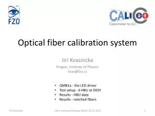
Optical calibration system for EUDET AHCAL module. Jaroslav Cvach IPASCR Calibration system for SiPM photodetectors QRLED driver photoelectron spectra QRLED driver behaviour in strong magnetic field Conclusions. Light distributed by notched fibres.

E N D
Optical calibration system for EUDET AHCAL module Jaroslav Cvach IPASCR Calibration system for SiPM photodetectors QRLED driver photoelectron spectra QRLED driver behaviour in strong magnetic field Conclusions
Light distributed by notched fibres Light distributed by microLED above scintillator distributed LEDs Flashing UVLED - 2 methods smd UVLED Institute of Physics ASCR, Prague Kobe University DESY Hamburg UNI Wuppertal Jaroslav Cvach, Prague
Notched fiber system Notched fibre routed at HBU0 • Advantage • Tuneable amplitude of LED light from 0 to 50 mips • Variation of LED amplitude does not affect the SiPM response readout • LED circuit and LEDs enable optical pulses with around 5ns width • Spread of light intensity from fibre notches can be kept under 20% • Disadvantage • LED with control unit not fully integrated in the detector volume • Notched fibre production is not trivial Jaroslav Cvach, Prague
6-LED QR driver Main Board = QMB6 • Consists of: • 6 QR LED drivers • 2 PIN PD preamps • CPU + commun. module CANbus • Voltage regulators • Temperature and voltage monitoring Jaroslav Cvach, Prague 4
Light distribution system with notched fibres • Light output from fibre via notches uniform over all 70 points (230 cm) • Approaching ±20% proposed limit of light variation • Notched fibre technology foreseen to improve Jaroslav Cvach, Prague
Setup for taking single p.e. spectra with notched fibre Light-tight box Notched fibre is laying on scintillator and taped to fix its position Sci + SiPM optical fibre LED QMB6 Preamp Jaroslav Cvach, Prague
P.E. spectra with increasing QRLED amplitude V2 Pedestal in red not in scale Jaroslav Cvach, Prague
P.E. spectra with increasing QRLED amplitude V2 Jaroslav Cvach, Prague
P.E. spectra with increasing QRLED amplitude V2 Jaroslav Cvach, Prague
P.E. spectra with increasing QRLED amplitude V2 Jaroslav Cvach, Prague
P.E. spectra with increasing QRLED amplitude V2 Jaroslav Cvach, Prague
P.E. spectra with increasing QRLED amplitude V2 QRLED generates beautiful p.e. spectra in SiPM Jaroslav Cvach, Prague
QMB6 in superconductive solenoid (magnetic field 0 to 4T) DESY Hamburg, February 2009 • Air core inductor can be sensitive to external magnetic field • We performed tests of QMB6 in variable magnetic field • 3 LED flash into 3 opto-fibre cables • CANbus cable and T-calib + Power in other cable • The setup was mounted on non-magnetic wooden paddle, to be moved in/out of solenoid bore. • Two black end-cups were used to optically screen the setup. Details of 4 Tmagnetic tests can be found at http://www-hep2.fzu.cz/calice/files/magnet5.jara_29.pdf Jaroslav Cvach, Prague
Setup for measurementsin magnet DUT solenoid Magnet control is not shown. Jaroslav Cvach, Prague
Start-up of measurements B 1% • Two test positions of QMB6 in the magnet bore with respect to field lines • Parallel • Slant • Long term stability of the system in 4 T • A few ‰ slope explained by the temperature variation at 0.1% level • Stable behaviour of the setup Jaroslav Cvach, Prague
QRLED (APD) response to B (t) Norm. Ampl. • The temperature (green line) was decreasing throughout the scan • Temperaturedependence of two APDs shows different slope • Due to different distance of APDs to temperature sensors (data sheet: gain spread < 1.5) • PIN diode temperature dependence stable • Extracted slopes from the linear fits were used to correct measured QRLED response Jaroslav Cvach, Prague
QRLED response to magnetic field 0 ÷ 4T Norm. ampl. magnetic field temperature 4T 1.01 2T 1.00 PIN APD1 APD2 0T Jaroslav Cvach, Prague
Implications from the observed light intensity variations with B B QMB6 has negligible sensitivity to B !!! Amplitude decreases linearly with B increase The same dependence for ramping up/down (ΔA/A)/ΔB ~ - 0.2%/T The same for parallel and slant positions Assuming magnetic field stability in ILD magnet at the level 5x10⁻⁴ (accuracy of the CMS magnetic field) relative light ampl. change ~ 10-6 Assuming magn. field inhomogeneity (CMS solenoid) ~ 0.3T/4T = 7.5% calibration light amplitude variation ≤ 2x10⁻⁴ in the magnet volume Compare to typical calibration light variation at the level of 10-1 (optical contacts) Jaroslav Cvach, Prague
EUDET Memo finished We conclude that the relative change of the amplitude of the QRLED driver does not exceed level of 3 per mile for 1 Tesla field change The amplitude time stability of the calibration light is better than 2x10⁻⁶ (part a day meas.) The maximal relative change of the calibration light amplitude inside the CMS solenoid from the QRLED driver will be smaller than 3x10⁻⁴ Jaroslav Cvach, Prague
Conclusions • Two optical methods for SiPM calibration in AHCAL under investigation • Notched fibres • Distributed LEDs • For each method UVLED driver has been developed • QRLED driver has tunable light amplitude and generates clear p.e. spectra • QRLED driver is not sensitive to magnetic field in the range 0 – 4 T • Both methods will be tested in HBU0 EUDET prototype Jaroslav Cvach, Prague
Back up Jaroslav Cvach, Prague
General mechanical concept AHCAL EUDET module Jaroslav Cvach, Prague
CMB = Calibration Monitoring Board • CMB used in AHCAL 1m3 prototype • 38 layers in AHCAL detector at at three TB facilitiesDESY/CERN/FNAL (2006 to 2009) • One CMB used in Japanese SciECAL detector (TB 2009) • 12 LEDs / 12PIN PD • Steering of amplitude and pulse width of LED by T-calib and V-calib signals • Temperature and voltage readout in slow control, CANbus control • Relevant links: • http://www-hep2.fzu.cz/calice/files/ECFA_Valencia.Ivo_CMB_Devel_nov06.pdf Jaroslav Cvach, Prague
Quasi-Resonant LED driver • Less RFI • PCB integrated toroidal inductor (~35nH) • Fixed pulse-width (~4ns) PIN signal 4ns/div LED current 1V => 1A 1App Jaroslav Cvach, Prague
QRLED Pedestal UVLED SiPM Jaroslav Cvach, Prague