Download
1 / 34
430 likes | 958 Views
Switch. Switch 는 Layer 2 Switch 와 Multi Layer Switch 로 구분된다 . CCNA 시간은 Layer 2 Switch . (Data-Link 계층 ) - Layer 2 Switch 는 포트별로 Collision domain 을 나눈다 . 하지만 하나의 Broadcast Domain 에 속해있다 . Router 와 차이점 1) Router 는 CPU-base (policy-base) Switch 는 ASIC(Application-

E N D
Switch • Switch는Layer 2 Switch와 Multi Layer Switch로 구분된다. • CCNA시간은 Layer 2 Switch. (Data-Link 계층) • - Layer 2 Switch는 포트별로 Collision domain을 나눈다. • 하지만 하나의 Broadcast Domain에 속해있다. • Router와 차이점 • 1) Router는 CPU-base (policy-base) Switch는ASIC(Application- • Specific Integrated Circuit)칩 기반이다. • 2) Router는Routing table, ARP-table을 확인 (IP address) • Switch는 MAC address table을 확인 (MAC address) • 3) Router는 자신이 모르는 목적지를 가진 packet과 Broadcast를 Drop. • Switch는 자신이 모르는 목적지를 가진 frame과 Broadcast를 Flooding.
Switch - Switch의 전송 방식 1) Store and Forward Frame을 전부 확인하고 다음 처리를 시작하는 방식. 목적지 주소, 출발지 주소, 에러발생여부를 확인하고 처리한다. error가 발생하면 Frame을 버리고 재전송을 요구. (error복구 능력이 좋다.) 하지만 다른 방식에 비해 느리다는 단점이 있다. 2) Cut-through 수신되는 Frame의 목적지 주소만 본 다음 바로 전송을 하는 방식. 처음 6 byte만 보고 전송하기 때문에 속도가 빠르지만 에러 복구 능력에는 약점을 가지고 있다. (거의 사용되지 않는다.) 3) Fragment-Free 위의 두 가지 방식을 결합한 방식, 처음 64 byte를 보고 전송하는 방식이다. Store and Forward 보다는 빠르고 Cut-through보다는 에러 감지 능력이 좋다고 볼 수 있다. (주로 64byte 쯤에서 에러가 많이 발생한다.)
Transparent Bridging • <Transparent Bridging> • - Ethernet Switch가 Frame을 수신하여 목적지로 전송하는 방식과 절차를 정의. • 즉, Switch가 수신한 Ethernet Frame을 참조하여 MAC address table을 생성 • 및 갱신하고 목적지로 전송할 때 사용하는 Protocol이 Transparent Bridging. • - Transparent(투명한)라는 용어는 ‘사용자가 의식하지 못하게 자동으로 동작한다.’ • 는 의미. • RSTP와 더불어 IEEE 802.1Q를 구성하며, 이 두가지가 Layer2 Switching의 • 핵심 구성요소. • Learning, Flooding, Forwarding, Filtering, Aging 과정이 모두 합쳐져 • Transparent bridging기능을 수행. • Routing table은 관리자가 설정으로 생성하지만 MAC address table은 • Switch가 자동 생성한다.
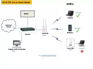
Transparent Bridging MAC address table A B 0260.8c01.1111 0260.8c01.3333 E0 E1 E2 E3 C D 0260.8c01.2222 0260.8c01.4444 • Initial MAC address table is empty
Transparent Bridging 1) Learning, Flooding MAC address table E0: 0260.8c01.1111 A B 0260.8c01.1111 0260.8c01.3333 E0 E1 C D E2 E3 0260.8c01.2222 0260.8c01.4444 • Station A sends a frame to Station C • Switch caches station A MAC address to port E0 by learning the source address of data frames • The frame from station A to station C is flooded out to all ports except port E0 (unknown unicasts are flooded)
Transparent Bridging 1) Learning, Flooding MAC address table E0: 0260.8c01.1111 E3: 0260.8c01.4444 A B 0260.8c01.1111 0260.8c01.3333 E0 E1 E2 E3 C D 0260.8c01.2222 0260.8c01.4444 • Station D sends a frame to station C • Switch caches station D MAC address to port E3 by learning the source Address of data frames • The frame from station D to station C is flooded out to all ports except port E3 (unknown unicasts are flooded)
Transparent Bridging 2) Forwarding, Filtering MAC address table E0: 0260.8c01.1111 E2: 0260.8c01.2222 E1: 0260.8c01.3333 A B E3: 0260.8c01.4444 0260.8c01.1111 0260.8c01.3333 E0 E1 X X D C E2 E3 0260.8c01.2222 0260.8c01.4444 • Station A sends a frame to station C • Destination is known, frame is not flooded
Transparent Bridging - Flooding MAC address table E0: 0260.8c01.1111 E2: 0260.8c01.2222 A B E1: 0260.8c01.3333 E3: 0260.8c01.4444 0260.8c01.1111 0260.8c01.3333 E0 E1 E2 E3 C D 0260.8c01.2222 0260.8c01.4444 • Station D sends a broadcast or multicast frame • Broadcast and multicast frames are flooded to all ports other than the originating port
Spanning-tree protocol - 단일 경로 - Server/host X Segment 1 Segment 2
Spanning-tree protocol - 단일 경로 - Server/host X Segment 1 Segment 2
Redundant Topology Server/host X Router Y Segment 1 Segment 2 • Redundant topology eliminates single points of failure. • Redundant topology causes broadcast storms, multiple frame copies, and MAC address table instability problems.
Redundant Topology Server/host X Router Y Segment 1 Segment 2 • Redundant topology eliminates single points of failure. • Redundant topology causes broadcast storms, multiple frame copies, and MAC address table instability problems.
Redundant Topology • <Redundant Topology의 문제점> • 1) Broadcast storms • 2) Multiple frame copies • 3) MAC address table instability
Broadcast Storms Server/host X Router Y Segment 1 Broadcast Switch A Switch B Segment 2 • Host X sends a broadcast.
Broadcast Storms Server/host X Router Y Segment 1 Broadcast Switch A Switch B Segment 2 • Switches continue to propagate broadcast traffic over and over
Multiple Frame Copies Unicast Server/host X Router Y Segment 1 Switch A Switch B Segment 2 • Host X sends an unicast frame to router Y • Router Y MAC address has not been learned by either switch yet
Unicast Unicast Unicast Multiple Frame Copies Server/host X Router Y Segment 1 Switch B Switch A Segment 2 • Host X sends an unicast frame to Router Y. • Router Y MAC Address has not been learned by either Switch yet. • Router Y will receive two copies of the same frame.
MAC Database Instability Server/host X Router Y Segment 1 Unicast Unicast Port 0 Port 0 Switch A Switch B Port 1 Port 1 Segment 2 • Host X sends an unicast frame to Router Y • Router Y MAC Address has not been learned by either Switch yet • Switch A and B learn Host X MAC address on port 0 • Frame to Router Y is flooded • Switch A and B incorrectly learn Host X MAC address on port 1
Solution: Spanning-Tree Protocol • 단일 경로로 구성할 경우 경로에 이상이 발생하면 통신이 이뤄지지 않는다. • 그럴 경우를 대비해 이중화 경로로 구성. • 하지만 다중 경로를 Ring구조로 구성할 경우에는 Looping 등의 문제 발생. • 이러한 문제들을 해결하기 위해 Spanning-Tree Protocol이 enable되어 있다. • <Spanning-Tree Protocol> • 다중화로 구성된 스위치에서 Looping발생을 방지하기 위해 하나의 경로를 • 제외하고 나머지 경로들을 차단했다가 사용되던 경로에 이상이 발생했을 경우 • 차단됐던 경로를 사용하는 알고리즘. x Block
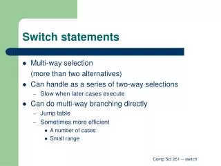
Spanning-Tree Operations • One root bridge per broadcast domain. • One root port per nonroot bridge. • One designated port per segment. • Nondesignated ports are unused.
BPDU(Bridge Protocol Data Unit) • Switch는 서로 BPDU를 교환해서 BPDU의 내용을 바탕으로 Looping • 없는 논리적인 경로를 구성한다. • <BPDU의 종류> • Configuration BPDU(설정 BPDU) • Switch는 Configuration BPDU를 이용하여 Root switch를 • 선출하고 각 Switch port의 역할을 지정. • Configuration BPDU는 Root switch가 만들고 다른 • Switch들은 수신한 BPDU를 다음 Switch로 중계. • 2) TCN BPDU • Switch가 연결된 Link에 변화가 생겼을 때 이것을 Root • switch에게 알리기 위해 사용. • * 설정 BPDU필드 중에서 Switch 네트워크의 논리적인 • 토폴로지를 결정하기 위해 Bridge ID, Path Cost, Port • ID값을 사용한다. <Configuration BPDU>
BPDU(Bridge Protocol Data Unit) 1) Bridge ID - 브리지나 Switch가 통신을 할 때 서로를 확인하기 위해 하나씩 가지고 있는 ID. - Bridge ID가가장 낮은 Switch가 Root switch로 선출된다. - BridgeID는 2Byte의 Bridge Priority(우선순위)와 6Byte의 MAC address로 구성. Bridge Priority의 default 값은 32768 이다.
Spanning-Tree Protocol Root Bridge Selection • BPDU (default = sent every 2 seconds) • Root bridge = bridge with the lowest bridge ID • Bridge ID = • In the example, which switch has the lowest bridge ID? Bridge Priority MAC Address
속도 경로값 10Mb Ethernet 100 100Mb Fast Ethernet 19 1000Mb / 1 GE 4 10 Gigabit Ethernet 2 BPDU(Bridge Protocol Data Unit) 2) Path cost (경로 값) - 다른 Switch와 연결된 link가 어떤 속도로 연결된 지 알아내기 위한 값. - IEEE에서 미리 정한 값을 사용. (속도가 빠를 수록 경로 값이 낮다.) - BPDU에서 사용하는 Path cost는 해당 Switch에서 Root 스위치까지의 경로를합한 값이다. 3) Port ID - BPDU를 전송하는 Switch의 Port 우선순위와 Port 번호로 구성. (기본값 128)
Spanning-Tree Operations • <STP의 동작 방식> • 1. 전체 Switch 중에 Root 스위치하나를 선택. • 2. Root 스위치가 아닌 다른 스위치들은 Root 포트를 하나씩 선택. • 3. 한 Switch의 segment마다 Designated(지정) 포트를 하나씩 선택. • 4. Root 포트와 Designated 포트가 아닌 포트는 alternate 포트로 선택되고 • Block 상태를 유지한다. 100baseT Designated port (F) Root port (F) Port 0 Port 0 Switch X Default priority 32768 MAC 0c0011111111 Switch Y Default priority 32768 MAC 0c0022222222 Root bridge Port 1 Port 1 x Designated port (F) Nondesignated port (B) 10baseT
Spanning-Tree Operations (1) Root 스위치 선출 - STP가 동작하면 Switch중 BridgeID가 가장 낮은 것이 Root 스위치로 선출. * BridgeID = 우선 순위(Priority) + MAC Address - Switch의 Priority 값이 동일하면 MAC 주소가 가장 낮은 Switch가 Root 스위치.
Spanning-Tree Operations (2) Root Port 선출 - Root 스위치가 선택되면 그 외 나머지 Switch의 port에서 Root port를 선택. - 다음 사항을 비교한 다음 선출. 1) Root 스위치의 ID가 가장 낮은 BPDU를 수신한 port. 2) Path cost가 가장 작은 Port. 3) 인접 Switch의 BridgeID가 가장 낮은 port. 4) 인접 Switch의 Port ID가 가장 낮은 port. 5) 자신의 Port ID가 가장 낮은 port.
Spanning-Tree Operations (2) Root Port 선출
Spanning-Tree Operations (3) Designated(지정)Port 선출 - Designated Port는 한 세그먼트(segment)당 하나씩 선택. Root 스위치의 모든 포트는 Designated port가 된다. - 다음 사항을 비교한 다음 선출. 1) Root 스위치의 각 Port. 2) 낮은 순위의 BPDU를 수신한 Port 3) Path cost가 낮은 Switch의 Port 4) BridgeID가 낮은 Switch의 port. 5) Port ID가 가장 낮은 port
Spanning-Tree Operations (3) Designated(지정)Port 선출
Spanning-Tree Port States • <Spanning-Tree Port States> • 1) Blocking State • 2) Listening State • 3) Learning State • 4) Forwarding State
Spanning-Tree Port States Spanning tree transits each port through several different states:
Spanning-Tree Port States 1) Blocking state 데이터 Frame을송수신 하지 않는 상태. 하지만 상대 측 Port에서 전송한 BPDU는 수신. 2) Listening state 해당 Port를 STP Forwarding 상태로변경시키기 위한 준비 단계. Listening 상태에서 Forwarding 시간 동안 특별한 문제가 없으면 Learning 상태로 변경 3) Learning state 해당 Port를 STP Forwarding 상태로 변경시키기 바로 전의 단계 Frame을 스위칭 시키기 위한 준비 작업을 한다. Forwarding 시간 동안 특별한 문제가 없으면 Forwarding 상태로 변경 4) Forwarding state Data Frame을 송수신하는 상태
Spanning-Tree Port States - STP에 따라 원래 통신을 하던 Link에 문제가 발생했을 경우 대기하고 있던 다른 Link로 대체하기까지 50초 정도의 시간이 걸린다. Blocking(20sec) listening(15sec) Learning(15sec) Forwarding 하지만 최근에는 여러 기술들로 이러한 약점들을 보완하고 있다. 1) Ether channel: 여러 개의 Link가 하나의 링크처럼 동작하게 하는 기술 (최대 8개 Link를 묶을 수 있다.) 평소에는 두 배의 속도를 낼 수 있고 하나의 Link가 끊어져도 기다리는 시간 없이 Link 가 유지된다. 2) Uplink fast: Link 복구 시간을 1분에서 약 2~3초 안에 가능하도록 만든 기술 3) RSTP, MSTP 등의 기술을 사용해도 Convergence 시간을 단축시킬 수 있다.