Download
1 / 6
60 likes | 223 Views
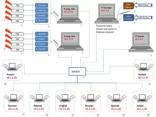
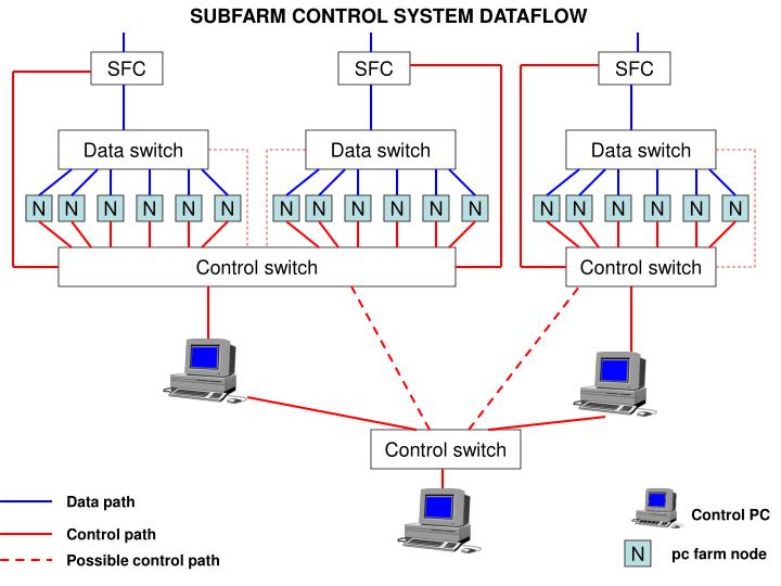
SUBFARM CONTROL SYSTEM DATAFLOW. SFC. SFC. SFC. Data switch. Data switch. Data switch. N. N. N. N. N. N. N. N. N. N. N. N. N. N. N. N. N. N. Control switch. Control switch. Control switch. Data path. Control PC. Control path. N. pc farm node. Possible control path.

E N D
SUBFARM CONTROL SYSTEM DATAFLOW SFC SFC SFC Data switch Data switch Data switch N N N N N N N N N N N N N N N N N N Control switch Control switch Control switch Data path Control PC Control path N pc farm node Possible control path
DAQ notes • Nodes: network interfaces up to 6 • a node can be: • pc control • tell 1 • farm node • level sorter unit • each node has an hardware @ associated to one interface (NIC). Each node has a IP @ which can be the same for different ethernet @. Each node can have a multicast mask. • each node has a field promiscous node (sort of flag can be one or 0): it indicates whether the node accepts packets not destinated to it. By default, this mode would be set on for switches and also nodes. • an IP @ can be for data or for control. We can consider the storage path as part of the DAQ. Same remarks for ehternet @. • a IPMA or BMC is an interface of a node. It has IP @es and Ethernet @. Related to IPMA, foresee a flag to specify if booting from this port is possible.
DAQ notes • routing tables: each switch has to know the IP@ and ethernet @ of the first level nodes (up and down) they are connected to and also the different IP@ and ethernet @ of the hops inbetween. • don’t forget the link type for checking paths.... • generating the path table dynamically. • An Ethernet @ is bound to 1 IP @ at most • But one IP@ can regroup several Ethernet @ (cf band link, aggregated link)
DAQ notes • Path tables generating: some definitions • a node is a device which sends commands and/or processes information. • a “switch” is a device which transfers data without modifying its content. (incl.buses) • a link is a physical cable between 2 couples (node, port number): • terminated-terminated nodes • terminated-intermediate nodes • intermediate-intermediate nodes. • a path is a sequence of links of the same type. It starts and ends with a terminated node. • a path is a cycle when it crosses a device twice.
DAQ notes • Ideas for the algorithms: • join the tfc_connectivity with itself iteratively • create temporary tables to store the intermediate results of the joins • a path is completed when it reaches the first terminated nodes. • we apply this principles for all terminated nodes belonging to a given subsystem. • we should avoid cycles: a script has to detect them. Shall we tell the user that there is a loop in its connectivity design? Security concern? Need to detect the loops • From the path tables, we deduce the routing tables for each switch : need to check misconfigurations cases (loop or non reachibility) • create a script to check that each FE board can reach any nodes and vice versa.