Download
1 / 16
260 likes | 548 Views
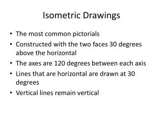
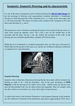
Isometric Pictorials. Isometric Pictorials. Isometric means equal measure . Three adjacent faces on a cube will share a single point. The edges that converge at this point will appear as 120 degree angles or 30 degrees from the horizon line.

E N D
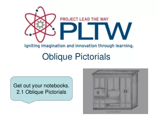
Isometric Pictorials Isometric means equal measure. Three adjacent faces on a cube will share a single point. The edges that converge at this point will appear as 120 degree angles or 30 degrees from the horizon line. These three edges represent height, width, and depth. 12 11 1 2 10 1200 9 3 1200 1200 4 8 7 5 6
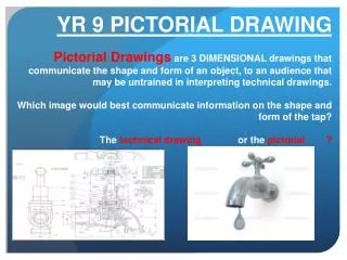
Proportion and Estimation Good sketching requires a sense of proportion, and the ability to estimate size, distance, angles, and other spatial relationships.
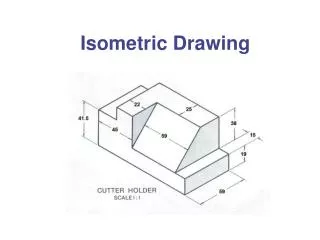
The Box Method The box method is a technique used in sketching to maintain proportionality. It starts with a sketcher envisioning an object contained within an imaginary box.
Isometric Sketching Step #1: Layout the box within which the isometric view will occur using points and construction lines.
Step #1: Constructing The Box • Finish by connecting the dots with light construction lines. Be sure to extend your lines past the corners • Connect the dots with light construction lines. Be sure to extend your lines past the corners • Locate corners of the maximum height and width of the box. • Locate the back corner of the top surface To find the angle of the depth and width – count over two … up one…
Isometric Sketching Step #2: Use points and construction lines to identify surfaces that are not parallel to the faces of the box.
Step #2: Outside Faces • Using construction lines connect the dots • Identify where the corners of the surface would touch the box.
Isometric Sketching Step #3: Trace out the visible edges of the part with thick, dark object lines.
Step #1: Constructing The Box Determine the overall dimensions of the object: • 6 units wide • 4 units tall • 4 units deep Use points and construction lines to layout the box.
Step #2: Outside Faces Use points and construction lines to identify the corners and edges of the object faces that occur on the surface of the box.
Step #2: Outside Faces cont. Before the sketch becomes too noisy with construction lines, trace out the visible edges identified thus far with object lines.
Step #3: Inside Faces Use points and construction lines to identify the corners and edges of the object faces that occur inside the box.
Step #3: Inside Faces cont. Trace out the remaining visible edges with object lines.
Step #4: Tonal Shading Decide where the light source is coming from, and add tonal shading to two of the three views with parallel lines drawn closely together. Increase the contrast by cross-hatching the lines on the darkest face.