Download

1 / 36
450 likes | 753 Views
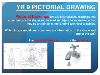
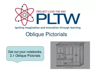
Oblique Pictorials. Oblique Pictorials. Object appears deeper than it actually is. More realistic view because depth does not appear distorted. Cavalier Oblique. Cabinet Oblique. Oblique Pictorials.

E N D
Oblique Pictorials Object appears deeper than it actually is More realistic view because depth does not appear distorted Cavalier Oblique Cabinet Oblique
Oblique Pictorials The following slides show the steps in creating oblique pictorials of the puzzle piece shown below. Imagine a glass box that encloses the entire object.
Oblique Pictorials Sketch a rectangle to represent the overall height and width of “the box” such that height lines are vertical and widths lines are horizontal. This will give a straight on view of the front of the object. Overall Height Overall Height Overall Width Overall Width
Overall Depth Oblique Pictorials Complete “the box” by sketching depth lines to the overall depth of the object at a given angle (45 degrees here). Cabinet is drawn half depth Cavalier is drawn full depth Full height Full height Full width Full width Cavalier Oblique Cabinet Oblique
The Box Method Height- Vertical Side View Depth 30° Front View Width 30°
Step 1: Construct the Box Layout the box that will contain the isometric view using points and construction lines Height- Vertical Front View Width 30° Side View Depth 30°
Step 2: Outside Faces Use points and construction lines to identify corners and edges of object faces that occur on box surface Height- Vertical Front View Width 30° Side View Depth 30°
Step 2: Outside Faces (continued) Trace visible edges of part with thick, dark object lines Height- Vertical Front View Width 30° Side View Depth 30°
Step 1: Constructing The Box Determine the overall dimensions of the object: • 3 units wide • 2 units tall • 2 units deep Height- Vertical Front View Width 30° Side View Depth 30° Use points and construction lines to layout the box.
Step 2: Outside Faces Use points and construction lines to identify corners and edges of object faces that occur on surface of the box Height- Vertical Front View Width 30° Side View Depth 30°
Step 2 – Outside Faces (continued) Before sketch becomes too congested with construction lines, trace visible edges with object lines Height- Vertical Front View Width 30° Side View Depth 30°
V.P. METHOD 1 – The Box Method 1. Sketch a horizontal line across the upper portion of the paperto represent the horizon, and identify a vanishing point. The vanishing point can be placed anywhere along the horizon line.
2. Sketch the front face of a “box” representing the overall size of the object. The front face is constructed with vertical height lines and horizontal width lines. Overall Height- Vertical Overall Width- Horizontal
3. Sketch construction lines from the corners of the front face of the “box” back to the vanishing point. Overall Height- Vertical Depth to VP Overall Width- Horizontal ALL EXTERIOR AND INTERIOR HEIGHT AND WIDTH LINES ARE PARALELL
ALL EXTERIOR AND INTERIOR HEIGHT AND WIDTH LINES ARE PARALELL 4. Sketch the visible back edges of the “box” to represent the overall size of the object. Overall Height- Vertical Depth to VP Overall Width- Horizontal Note that you will have to estimate the depth of the object.
5. Locate points and construction lines to identify corners and edges of the object on the surface of the “box”. Depth to VP Overall Height- Vertical Overall Width- Horizontal ALL EXTERIOR AND INTERIOR HEIGHT AND WIDTH LINES ARE PARALELL
6. Use object lines to trace over the edges of the object on the visible surface of the “box”. Overall Height- Vertical Depth to VP Overall Width- Horizontal ALL EXTERIOR AND INTERIOR HEIGHT AND WIDTH LINES ARE PARALELL
Two-point Perspective 1. Sketch a horizontal line across the upper portion of the paperto represent the horizon, and identify two vanishing points. The vanishing points should can be placed toward each end of the horizon line.
Two-point Perspective 2. Sketch a vertical construction line to represent the front edge of the object. The construction line can be drawn below, above, or through the horizon line. Front Edge
Two-point Perspective An imaginary “box” encloses the entire object 3. Locate two points on the construction line to represent the top and bottom corners of the “box” within which the object will be sketched. FRONT-SIDE EDGE
Two-point Perspective ALL EXTERIOR AND INTERIOR HEIGHT LINES ARE VERTICAL AND PARALELL 4. Sketch a construction line from each point on the vertical line to each vanishing point. Width to VP 1 Depth to VP 2
Two-point Perspective ALL EXTERIOR AND INTERIOR HEIGHT LINES ARE VERTICAL AND PARALELL Width to VP 1 5. Sketch points and vertical construction lines to represent the overall width and depth of the object. You will need to estimate the location of these to make the box proportional. Depth to VP 2
Two-point Perspective ALL EXTERIOR AND INTERIOR HEIGHT LINES ARE VERTICAL AND PARALELL Width to VP 1 Depth to VP 2 6. Sketch construction lines to represent the top back edges of the “box”.
Two-point Perspective ALL EXTERIOR AND INTERIOR HEIGHT LINES ARE VERTICAL AND PARALELL Width to VP 1 Depth to VP 2 7. Sketch points and construction lines to identify the edges of the object faces that occur on the visible surfaces of “the box.”
Two-point Perspective ALL EXTERIOR AND INTERIOR HEIGHT LINES ARE VERTICAL AND PARALELL Width to VP 1 Depth to VP 2 7. Sketch points and construction lines to identify the edges of the object faces that occur on the visible surfaces of “the box.”
Two-point Perspective ALL EXTERIOR AND INTERIOR HEIGHT LINES ARE VERTICAL AND PARALELL Width to VP 1 Depth to VP 2 7. Sketch points and construction lines to identify the edges of the object faces that occur on the visible surfaces of “the box.”
Two-point Perspective ALL EXTERIOR AND INTERIOR HEIGHT LINES ARE VERTICAL AND PARALELL Width to VP 1 Depth to VP 2 7. Sketch points and construction lines to identify the edges of the object faces that occur on the visible surfaces of “the box.”
Two-point Perspective ALL EXTERIOR AND INTERIOR HEIGHT LINES ARE VERTICAL AND PARALELL Width to VP 1 Depth to VP 2 8. Trace over the construction lines to delineate the edges of the object faces that occur on the visible surfaces of “the box.”
Sketching a Multi-View Drawing Step 1 - Layout the boxes within which the individual views will occur using points and construction lines. TOP FRONT RIGHT SIDE
Box Dimensions TOP DEPTH front height + spacing + top depth= overall height TOP SPACE RIGHT SIDE FRONT FRONT HEIGHT front width + spacing + side depth= overall width FRONT WIDTH SPACE SIDE DEPTH