Download
1 / 7
70 likes | 80 Views
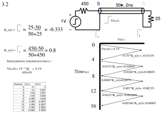
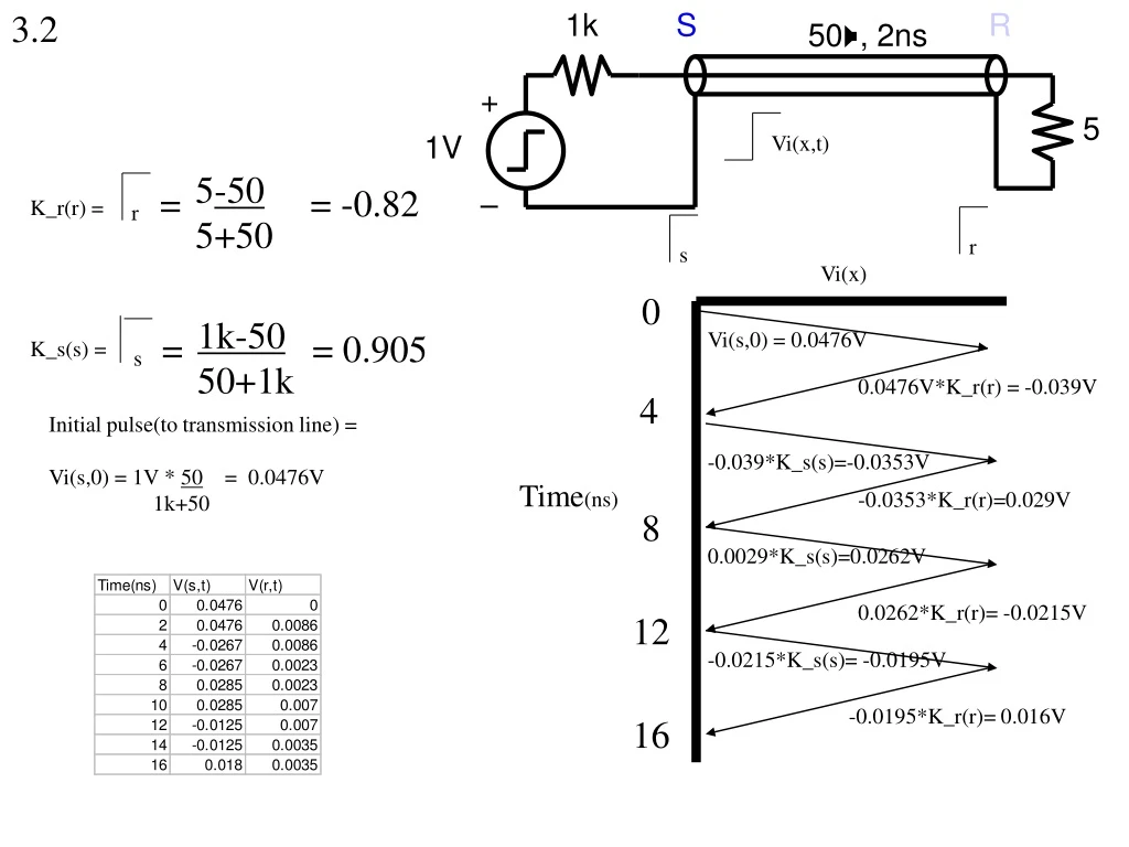
3.2. 1k. S. R. +. –. 50 W , 2ns. 5. 1V. Vi(x,t). 5 -50 5+50. =. = -0.82. K_r(r) =. r. r. s. Vi(x). 0. 1k-50 50+1k. =. = 0.905. Vi(s,0) = 0.0476V. K_s(s) =. s. 0.0476V*K_r(r) = -0.039V. 4. Initial pulse(to transmission line) = Vi(s,0) = 1V * 50 = 0.0476V

E N D
3.2 1k S R + – 50W, 2ns 5 1V Vi(x,t) 5-50 5+50 = = -0.82 K_r(r) = r r s Vi(x) 0 1k-50 50+1k = = 0.905 Vi(s,0) = 0.0476V K_s(s) = s 0.0476V*K_r(r) = -0.039V 4 Initial pulse(to transmission line) = Vi(s,0) = 1V * 50 = 0.0476V 1k+50 -0.039*K_s(s)=-0.0353V Time(ns) -0.0353*K_r(r)=0.029V 8 0.0029*K_s(s)=0.0262V 0.0262*K_r(r)= -0.0215V 12 -0.0215*K_s(s)= -0.0195V -0.0195*K_r(r)= 0.016V 16
3.10 + 1V – 50W, 2ns 10W s 10-50 50+10 r = = -0.66 K_r(r) = r Initial pulse(to transmission line) = Vi(s,0) = 1V * 50 = 0.833V 10+50 1V Vi(x,t) At the beginning of time, V(r)=0V. Assume that both diodesare not conducting. In this case, V(r) looks like an open circuit.A wave of 0.83V hits the end of the line. Nominally, for an opencircuit, the wave will get reflected back with K_r(r)=1. That meansthat V(r)=1.66V. However, we know that once V(r)=1V, the topdiode becomes conducting, forcing V(r)=1V. Therefore, it is impossible for 0.83V to reflect back. Instead, a wave of 1-0.83V=0.17V is reflected backwards to V(s), in order for V(r)=0.83V+0.17V=1V. This 0.17V is now a traveling wave back to the source, where it sees a negative reflection coefficient, so that a -0.66*0.17=-0.112V wave now is heading towards V(r). However, when this wave hits V(r), since the top diode is conducting, K_r(r)=-1. So this -0.112V gets reflected back as a wave of magnitude 0.112V. This basically “rings” up the source voltage, while V(r)rings up with the inital step voltage. s Vi(x) r 0 Vi(s,0) = 0.833V 0.17V 4 0.17*K_s(s)=-0.112V -0.112*K_r(r)=0.112V 8 0.112*K_s(s)=-0.074V -0.074*K_r(r)= 0.074V 12 0.074*K_s(s)= -0.049V -0.049*K_r(r)= 0.049V 16 Time(ns)
You can also consider the reflection process with currents as opposed to voltages ringing along the line.The initial pulse puts a current of 1V/60 = 16.6mA into the line. At the far end, which is terminated bythe diodes, 3.4mAreflects back and 13.2mA goes into the diode. When the 3.4mA reaches the source, -2.2mA reflects back. When this gets to the far end, it reduces the 13.2mA to 11.0mA, but since this is greater than 0 the diode remains conducting and a negative reflection occurs -- reducing the diode current to 8.8mA. And so on. The following spice waveform shows what happens when the diode connected system is input with a much slower input step edge.(200ps vs 10ps) Since the input voltage doesn’t rise to 1V fast enough, the input into the line will not be an immediate 0.83V, but instead, a slower rise to 0.83V. This means that the reflection at the end of the line will see an open circuit for longer time, since the pulse doesn’t rise to 0.83V that fast. In this manner, you see the reflected pulses from the transmitter termination go to 1V and then settle back to the values that were calculated above, due to the finite time of the input rise time.