Download
1 / 13
150 likes | 361 Views
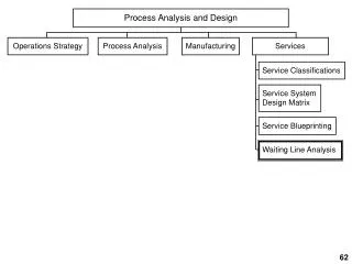
PMSM Design and Loss Analysis. Liping Zheng 07/23/2003. PMSM Configuration. Litz-wire: 1.78 mm x 2.27 mm 50 strands @ AWG 30 Gap : 0.5 mm Stator Di: 25.5 mm Do: 38 mm Length: 25.4 mm Shaft diameter: 16 mm.

E N D
PMSM Design and Loss Analysis Liping Zheng 07/23/2003
PMSM Configuration Litz-wire: 1.78 mm x 2.27 mm 50 strands @ AWG 30 Gap : 0.5 mm Stator Di: 25.5 mm Do: 38 mm Length: 25.4 mm Shaft diameter: 16 mm No major shaft stress problem if we select high stress shaft material.
Progress • Got the Litz-wire with rectangular profile. • Total 22 lb. • Found the permanent magnets (PM) manufacturer to fabricate the special shape PM with 0.001 in (0.025 mm) tolerance. • According to new PM profile, adjust the winding configuration and perform all simulations. • Filter inductor preliminary design.
Shaft Cross Section Shaft Cross-section Ø 16 5 2.5 2.5 5 (mm) Courtesy of Dipjyoti Acharya All Dimensions are in mm
Airgap Flux Density • Low harmonics of the normal flux density. • Tangent flux density is a little large due to large airgap.
Simulated Torque 1.5% ripple • Winding pitch is modified from 12/15 to 10/15. • Simulated back EMF=12 V • Use Generator mode to simulate Torque. • Load current = 60.8 A
Inductor Design Constraints:
DC Filter Inductor • Negligible core loss, proximity loss. • Copper loss dominated. • Flux density chosen simply to avoid saturation. • Airgap is employed.
AC Filter Inductor • Core loss, copper loss, proximity loss are all significant. • Flux density is chosen to reduce core loss. • A high-frequency core must be employed. • An air gap is employed.
P Core Structure-p66/56 d1=66.29 mm d2=54.51 mm d3=28.19 mm h1=57.3 h2=43.28 Ferrite type: MnZn (manganese and zinc) Material :3C81,3C91
Use P66/56 core Copper loss 1.2W
Loss of Filters • Copper Loss (3 turns): • 1.2W • Core loss (3C91): • 50mW/cm3 @ 10KHz (from manufacturer’s data). • Estimated 10mW /cm3 @ 3.3KHz. • Estimated 20mW /cm3 considering harmonics. • The volume is 124 cm3 2.48W • Total loss of the filters (3 inductors): • 3x (1.2+2.48)=11W.
PMSMLoss Future work Motor Efficiency: Control Efficiency: Total Efficiency: