Download
1 / 19
190 likes | 326 Views
HV-LV-DCS Status. DCS barrel: G. Polese and P. Paolucci DCS endcap: A. Cimmino and P. Paolucci HV & LV: D. Lomidze and P. Paolucci NEWS DCS Endcap Integration DCS Barrel Integration see Giovanni talk 1 PC with barrel project working at 904 1 PC with endcap project at 904 asap

E N D
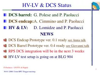
HV-LV-DCS Status • DCS barrel: G. Polese and P. Paolucci • DCS endcap: A. Cimmino and P. Paolucci • HV & LV: D. Lomidze and P. Paolucci NEWS • DCS Endcap Integration • DCS Barrel Integration see Giovanni talk • 1 PC with barrel project working at 904 • 1 PC with endcap project at 904 asap • HV-LV test setup is going on at BLG 904 P. Paolucci - I.N.F.N. di Napoli
EASY bus 48 V - power IN OUT OUT 48 V - service EASY Crate A3486 AC/DC has 2 channels of 2 KW each * 3 boards with safety factor 2 ** 6 boards with safety factor 2 P. Paolucci - I.N.F.N. di Napoli
EASY crate back schema P. Paolucci - I.N.F.N. di Napoli
EASY bus 48 V - power IN OUT OUT 48 V - service EASY crate connection schema P. Paolucci - I.N.F.N. di Napoli
S1H02-06 EASY 1 2 3 456 - EASY 1 2 3 45 6 - turbine 4U fan tary fan tary heat exchange heat exchange 8U 36 input ch. 24 ch. 36 ch. sect 05-06 HV distributor sect 11-12 HV distributor sect 03-04 HV distributor sect 09-10 HV distributor sect 01-02 HV distributor sect 08-07 HV distributor 12 ch. 24 ch. 44 U 36 input ch. 8U 48 output ch. 48 output ch. EASY 1 2 3 4 - - - 24 input ch. 8U fan tary heat exchange spare HV distributor 2U air deflector NEW USC55 barrel HV system "wheel" crate schema • General Information • max HV EASY board: 7 ch. • max EASY crate: 42 ch. • HV distributor: • 32 input ch (2 sectors) • 16 output ch. • Rack height tot: 56 U • turbine 4 U • air defl. 2 U • Rack available height 50 U Total: 72/96 ch. • We need (per wheel/rack) • 72 ch 12 HV boards (reduced*) • 96 ch 16 HV boards (final) • 3 EASY crate (4-4-4) (6-6-4) • 3 FAN crates + heat exchange • 6 distributors + 1 RB4-sect4 join • * RB3 and RB4 joint together (12 + 12) P. Paolucci - I.N.F.N. di Napoli
AC/DC 48V power AC/DC 48V service AC/DC 48V power AC/DC 48V power 3U 3U 3U 3U 2x2 KW (spare ?) 2x2 KW 2x2 KW 2x2 KW NEW USC55 HV barrel racks composition • HW numbers • 15 EASY crates • 60-80 HV boards A3512 • 360-480 HV channel • 30+4 HV distributors • 2 SY1527 mainframes • 3 or 4 AC/DC 48 V - A3486 (or A3485) 136 components S1H07 turbine 4U SY1527 HV 8U SY1527 LV 8U 800 cables • CABLE numbers • EASY power (direct) 5 • EASY power (daisy) 10 • EASY service (direct) 2 • EASY service (daisy) 14 • Branch Contr. (direct) 2 • Branch Contr. (daisy) 14 • Fan unit contr. 15 • EASY Ground - 15 • SY1527 ground - 2 • 480 HV input + 240 HV out 34U 2U air deflector P. Paolucci - I.N.F.N. di Napoli
HV-LV status • Setup at 904 is finished. • MTCC setup is almost ready • Setup ready for Cosmic Challenge in March 06 • Move from 904 to SX5 in April 06 P. Paolucci - I.N.F.N. di Napoli
LV MTCC setup 2 LV EASY crates OK • 2 LV boards A3009 (2 sectors) • 1 LV board A3009 (1 sector) • Short cables and connections are OK • Waiting for lengths for long cables. • 2 Control cables P. Paolucci - I.N.F.N. di Napoli
HV MTCC setup 1 HV EASY crates OK • 4 HV boards A3512 (3 sectors) • Short cables and connections are OK • Waiting for lengths for long cables. • 3 multi-conductors cables P. Paolucci - I.N.F.N. di Napoli
RPC DCS status • Barrel and Endcap projects are ready • Two PCs running the projects are at 904 • Integration with CMS DCS is almost ready, some common problems still to fix • RPC DCS will be ready for May 2006 P. Paolucci - I.N.F.N. di Napoli
Next Steps • Define the hardware of the endcap system • Install the system at SX5 • Build and install long cables • Test it in April-May to be ready for CC P. Paolucci - I.N.F.N. di Napoli
LV – EASY – 12 ch. W+1 LV LV – MAO – 1 ch. HV – EASY – 24 ch. LV – EASY – 24 ch. LV – MAO – 1 ch. HV HV HV HV LV LV W+2 HW schema for CC Control LV RPC - SY1527 BC LV BC LV BC HV AC/DC Control HV PWR HV HV multicond. 10 ch. HV – MAO – 2 ch. AC/DC AC/DC PWR HV PWR HV 48 V – service LV 380 3-phase 380 3-phase Balcony Barack Detector
RPC FSM Hierarchy • Since the last meeting: • The endcap is up to date with the barrel and the two systems are proceeding in parallel • Tests on CPU and RAM usage have brought us to reduce the number of CUs. Limiting to the top two levels. Possibility of using only wheels or disks in standalone mode as lower nodes. • Introduction of a new level in the hierarchy. This will allows a better partitioning of the system. • The two systems are under a single top node as required by the CMS DCS Integration guidelines. The two systems can also work standalone. CMS_RPC Barrel RPC Endcap RPC CU Wheel Disc Barrel Supervisor Endcap Supervisor Sector Ring LU Chamber Chamber Channel Channel HV/LV Sys HV/LV Sys Device level Device level NEW LEVEL P. Paolucci - I.N.F.N. di Napoli
RPC DCS for MTCC • Since the last meeting: • Intensive (2 weeks) test with HW at 904 building induced us to perform Minor changes to the FSM schema • Redesign Hierarchy and distribution on more PCs. • We are investigating How distribute the HW component on more PCs and the resources needed. CMS_RPC PC01 Supervisor PC02 Barrel RPC Endcap RPC Wheel Disc Sector Ring Chamber Chamber • DATABASE • We are able to receive and upload the HW setup into the project from Oracle DB • We are able to download different configuration setup from DB for ON and StandBy states HV/LV Sys HV/LV Sys Device level Conf. DB Device level Channel Channel PC03.. PC04.. P. Paolucci - I.N.F.N. di Napoli
RPC DCS Integration Status • We were successful in creating a first version of the CMS RPC sub-detector SUPERVISOR component using the tool provided by the JCOP framework. The RPC component contains both Endcap and Barrel trees, but it has been designed has two components that can work on different PCs. • We accessed the Configuration DB . We are able to read from and write in it (in a private Oracle DB) using custom scripts with Framework functions. • We still need to • - know the coordinates of the DB we are going to use for the CC and test the best way to access the DB (different solutions are possible) • - finish to prepare the hardware component (march 06) • - work on the condition DB • - temperature monitoring (waiting for JCOP FW) P. Paolucci - I.N.F.N. di Napoli
CMS RPC Gas Monitor Frascati Group • A monitoring system of the RPC work point which is able to provide much faster and sensitive response than the CMS RPC system. • Monitor efficiency and charge continuously • If work point changes, alarm goes off and DSC systems (GC,probes, etc) verify what the change of work point is due to.
MONITOR RPC PAD RPC PAD RPC PAD source RPC PAD RPC PAD RPC PAD RPC PAD RPC PAD RPC PAD source RPC PAD RPC PAD RPC PAD RPC Gas Monitor v.1 Slow Ctrl GC, p/T/RH/Ph REFERENCE CMS RPC PAD RPC PAD RPC PAD source RPC PAD RPC PAD C2H2F4/SF6 /i-C4H10 /H2O RPC PAD
DAQ system for the CMS RPC Gas Monitor The system must be integrated in the Slow Control (SC) of CMS RPC. This implies to follow the CMS standards for DAQ: PVSS or xDAQ We are evaluating different solutions in order to minimize the effort in the integration with CMS Slow Controls Our present option is to use a system fully based on PVSS both for P,T, RH and HV, and both for ADC, (+TDC...+ other VME module) readout based on VME standard Standalone systems (PICO, ACQIRIS, etc) do not seem to offer the same versatility of a VME system and comparable performances VME readout via PVSS ?
PVSS CMS SlowControl Temptative DAQ architecture for the CMS RPC Gas Monitor CAEN HV system PVSS Pressure, temperature & humidity sensors ? VME modules for RPC pads readout • Controller VME CAEN • ADC V1724A - 8CH 14BIT 100MHZ • Scaler V830AC - 32 Channel 32 Bit • Crate VME8002 MINI VME64 09 SLOT • TDC V1290A - 32 Ch /25 psec CMS SlowControl