Download
1 / 15
150 likes | 162 Views
P10022 Transcutaneous Signal Transmission for LVAD. February 19, 2009 Sara Carr, Carl Hoge, Keith Lesser, Robert MacGregor, Oxana Petritchenko. Left Ventricular Assist Devices (LVAD). Typically LVADs are used while a patient is awaiting for heart transplant

E N D
P10022 Transcutaneous Signal Transmission for LVAD February 19, 2009 Sara Carr, Carl Hoge, Keith Lesser, Robert MacGregor, Oxana Petritchenko
Left Ventricular Assist Devices (LVAD) • Typically LVADs are used while a patient is awaiting for heart transplant • They help the LVAD to pump blood throughout the body • Depending on patient, they can be implanted for months or years • Eventually will have ability to become a permanent solution
Dangers of Wired Systems • Wired systems pose a danger to heart pump patients • Around 40% deaths in patientscome from infection • Most susceptible to infection aftersurgery or traumatic event • Wired systems also limit mobility, and may cause discomfort
Final Product: Signal Transmission Programming Wires PIC Inner Case VoltageDividers PIC Heat Shrink Boots Outside case VoltageRegulator DAC PIC Signal cable(Through Skin) Relay Switch Power Cable Inner PCB Grommets Outside PCB DisplayPort Connector
Final Product: Wireless Power Secondary Coil Primary Coil Voltage Regulator H-Bridge Rectifier Pulse Generator Powered LED
Testing: Cable • Cables measured at multiple locations • 300% thinner • Weights applied to wire between supports spaced at a fixed distance • 370% more flexible Old Cable: Diameter = 8 mm New Cable: Diameter = 2.7 mm
Testing: Signals HESA Signal Out • Testing • Position monitor signals: 0-600Hz 0-3.3V • PWM control signals: 20kHz 0-100% Duty Cycle • Motor Controller signal: 50Hz 0-100% Duty Cycle • Results • Position monitor and PWM control signals were accurately transmitted with delay of 32μsec • Method used to transmit motor controller signal was not sufficient HESA Signal In PWM Signal In PWM Signal Out Motor Controller Signal In Motor Controller Signal Out
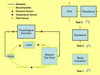
Testing: Power Efficiency • Testing • Coils were set at different distances between 0.5cm – 2cm • Different loads were placed at the output to measure output power • Results • Efficiency over full system was between 10-36% • Efficiency over coils was between 16-28% at 0.5 cm
Testing Power Efficiency • Various materials were placed between the coils to study performance over a 15Ω load and spacing of 0.75cm • Materials Used • Paper • Cardboard • Aluminum Foil • Magnet
Project Status • Size and flexibility needs met • Wireless power concept proven to work • 10% efficiency over system • 35% over the coils • 12 of 13 signals met performance requirements • Motor control signal duty cycle not within 5% of target value • Sampling rate of some signals is too slow
Future Improvements • Modify PIC firmware to be capable of sampling all signals at the correct rate • Implement PCBs without jumper wires • Modify circuitry to transmit motor control signal with more accuracy. • TET efficiency • Alternative H-Bridge to dissipate less heat • Alternative H-Bridge/driver circuit to run at ~170 Hz • Packaging