Download
1 / 29
290 likes | 297 Views
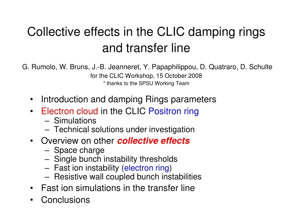
Collective effects in the CLIC damping rings and transfer line G. Rumolo, W. Bruns, J.-B. Jeanneret, Y. Papaphilippou, D. Quatraro, D. Schulte for the CLIC Workshop, 15 October 2008 * thanks to the SPSU Working Team. Introduction and damping Rings parameters

E N D
Collective effects in the CLIC damping rings and transfer lineG. Rumolo, W. Bruns, J.-B. Jeanneret, Y. Papaphilippou, D. Quatraro, D. Schultefor the CLIC Workshop, 15 October 2008* thanks to the SPSU Working Team • Introduction and damping Rings parameters • Electron cloud in the CLIC Positron ring • Simulations • Technical solutions under investigation • Overview on other collective effects • Space charge • Single bunch instability thresholds • Fast ion instability (electron ring) • Resistive wall coupled bunch instabilities • Fast ion simulations in the transfer line • Conclusions
Updated list of parameters last column From Y. Papaphilippou, in CLIC-Parameter-WG
More parameters needed for the collective effects (I) From the present DR design, thanks to Y. Papaphilippou • Average beta functions together with the emittances define the average bunch transverse sizes over tha arcs and the wigglers • Number and length of dipoles and wigglers define the fraction of the ring covered by those elements and therefore ascaling factor for the e-cloud density to be used in instability simulations
More parameters needed for the collective effects (II) D. Schulte, R. Wanzenberg, F. Zimmermann, in Proceed. ECLOUD‘04 Design of the vacuum chamber with antechamber in the arcs (it has double sided ante-chamber in the wigglers) Photoemission yields The antechamber absorbs 90 to 99.9% of the synchrotron radiation and gives a photoemission yield in the main chamber 10 to 1000 times lower than in a design w/o antechamber
Electron cloud build up: a multi-bunch process... Principle of the multi-bunch multipacting. Electrons can be generated via photoemission, rest gas ionization or beam loss at the chamber walls. They then multiply due to the seconday emission process
Effects of the electron cloud on the beam: • Tune shift • The tune increases along a train of positively charged particle bunches because the bunches at the tail of the train feel the strong focusing effect of the electron cloud formed by the previous bunches. • Electron cloud instability in rings • Coupled bunch phenomenon: the motion of subsequent bunches is coupled through the electron cloud and the amplitude of the centroid motion can grow. • Single bunch phenomenon: the motion of head and tail of a single bunch can be coupled through an electron cloud and give rise to an instability Tune shift along the train as well as instabilities affecting only the last bunches of long trains have been observed in several machines (SPS, KEKB-LER, Cesr-TA), clearly pointing to the electron cloud as source of these phenomena.
Electron cloud build up in the arcs (simulations with Faktor2) Central electron density in a radius of 5sx x 5sy 3 3 • Low maximum SEY does not cause high density electron cloud build up • High maximum SEY causes exponential rise, which can saturate over few turns if the PEY is also sufficiently high
Electron cloud build up in the wigglers (simulations with Faktor2) Central densities for different PEYs and SEYs 3 3 • The electron cloud in the wigglers can have high density values if • The PEY is high enough (i.e., more than 0.01% of the produced radiation is not absorbed by an antechamber or by special absorbers), even if the SEY is low • The SEY is above 1.3, independently of the PEY 3
Summary of the density values obtained from build up simulations Dipole chamber For these values there is basically a negligible electron cloud Wiggler chamber Here the values do not change even with a lower PEY • To model an integrated effect over one turn, these values have to be scaled by: • Wigglers (total wiggler length)/circumference = (76 x 2)/365 = 0.41 • Arcs (total arc length)/circumference = (96 x 0.545)/365 = 0.143
Instability simulations to check beam stability (simulations done with HEADTAIL) • In case of electron cloud build up, we assume these density velues in arcs and wigglers: rwig = 1.8 x 10¹³ m-3 rdip = 3 x 10¹¹ m-3 • The beam is strongly unstable * Vertical centroid motion * Vertical emittance evolution
Against the electron cloud..... • If there is electron cloud in the CLIC-DR, the beam becomes unstable! • Conventional feedback systems cannot damp this instability (wider band needed) • It is necessary to find techniques against the formation of the electron cloud • Several mitigation techniques are presently under study: • Low impedance clearing electrodes • Solenoids (KEKB, RHIC) -however only usable in field free regions! • Low SEY surfaces • Grooved surfaces (SLAC) • NEG and TiN coating • New coatings presently under investigation (SPS) Carbon coatings, studied by the SPS Upgrade Working Team, seem very promising and a possible solution.... (M. Taborelli‘s talk this afternoon)
Evolution of CNe9 over 1 month SEY of CNe Courtesy M. Taborelli from SPSU-WT Details in M. Taborelli‘s talk in the afternoon 2h 3d 8d 15d 23d The maximum SEY starts from below 1 and gradually grows to slightly more than 1.1 after 23 days of air exposure. The peak of the SEY moves to lower energy.
Measurements inside the SPS confirm the lab measurements! NEG and CNe exhibit no electron cloud activity in the SPS !!! Details in M. Taborelli‘s talk in the afternoon • Perhaps this is the strategy to get rid of electron cloud issues ??... • However, need to check the PEY of these coated surfaces in order to fully validate their use for DRs as well! • Tests planned at ESRF or in Cesr-TA
SPACE CHARGE (I) • Tune spread induced by space charge can be estimated analytically integrating the space charge induced gradient all around the lattice to take into account of the beam size change due to the betatron modulation • The horizontal tune spread is in the order of 0.01 • The effect is obviously much stronger in the vertical plane because the beam is smaller in this plane
SPACE CHARGE (II) • Space charge can also be responsible for emittance growth • The effect can be estimated simulating the multi-turn transport of a bunch through the CLIC damping ring applying several space charge kicks randomly selected in the lattice • The simulations have been carried out with the HEADTAIL code for an increasing number of kicks per turn and running 10 different seeds for each case • Starting from a number of kicks N>60, the value levels off at ~8-10%, which would still be not acceptable.
SINGLE BUNCH INSTABILITIES • Longitudinal • The Boussard criterion (including in the formula the suppression factor (b/sz)2) would give a maximum impedance value of ~5W • . • Transverse • The TMCI threshold is given by the formula below • The CLIC-DRs are in short bunch regime, and the formula translates into a tolerable impedance value of ~15 MW/m if wr=2p x 6 GHz
COUPLED BUNCH INSTABILITY FROM RESISTIVE WALL • Transverse ~1ms • Pessimistic estimate because: • wigglers only cover half of the ring, which gives possibly a factor 2 • instability rate has to be scaled by nb/M, because the formulae assume a uniformly filled ring.
FAST ION (I) Ions: residual gas ionization CO molecule CO+ ion Nee- beam l ≈ 4sz The ion cloud can affect the motion of the bunches and an unstable ion-electron coupled motion can be excited The ions produced by gas ionization can be focused by the electric field of the following bunches and they accumulate in the vicinity of the beam (trapping condition) Two-stream instability
FAST ION (II) The ions trapped around the beam are those having a mass number above: This means that molecules like N2, CO, H2O are trapped around the beam Trapped ions cause tune spread (p=1 nTorr) and a fast instability having a rise time of about 1.1 ms, calculated with the following formula.
FAST ION IN THE TRANSFER LINE • To study the fast ion instability in a transport line, we have developed FASTION • Multi-bunch code, ions and electrons are macro-particles • Ions of an arbitrary number of species are created at each bunch passage and propagated through the train • Line is made of a sequence of FODO cells, two kicks per FODO cell, or the lattice is passed through an external file. Acceleration along the line can be included. • Electromagnetic interaction: the ions are kicked by the passing bunches and the bunch macro-particles feel the effect of the ion field F O D O Bunch n+1 Bunch n y s x ion electron Cell j Kick 2 Kick 1
Some parameters of the transfer line • We have carried out simulations of fast ion instability using the following parameters • Beam energy is 9 GeV. Length is 20 km. • Residual gas pressure is 1 nTorr for each species. Only two species of ions have been considered (CO and H2O) • Bunch population is 4 x 10⁹ (3.7 x 10⁹) • Bunch spacing is 500 ps • Number of bunches (Nb) is 300 • Normalized emittances are 680,10 nm (660,10) • Line is made of 500 FODO cells (each 40m long) with a phase advance of 70o
Trapped ions in the transfer Line • The motion of two sample ions (of two different species, CO and H2O) show that they are trapped around the beam s
Instability in the transfer line (movie) • A coherent instability in the vertical plane develops along the line for a pressure of 1 nTorr s
Instability in the transfer line (snap-shots) • A coherent instability in the vertical plane develops along the line for a pressure of 1 nTorr s
Emittance growth along the transfer line (movie) • The instability in the vertical plane also causes emittance growth (p=1 nTorr) s
Emittance growth along the transfer line (snap-shots) • The instability in the vertical plane also causes emittance growth (p=1 nTorr) s
SPACE CHARGE in the TRANFER LINE • The spread in phase advance per FODO cell induced by space charge in the long transfer line can be estimated analytically integrating the space charge induced gradient over the cell to take into account of the beam size change due to the betatron modulation • The effect can be critical, and therefore needs to be quantified, in the vertical plane, because the beam is smaller in this plane • Preliminary tracking simulations show no significant space charge induced emittance growth over the line length.
Conclusions (I) • The electron cloud (build up and instability) in the positron ring poses constraints on PEY and SEY of the beam pipe. • Wigglers should be designed such as to be able to absorb 99.9% of the produced synchrotron radiation (new design under study) • The maximum SEY should be kept below 1.3 • Special chamber coatings (under study) could be required • Space charge • Causes a very large tune spread in the vertical plane (0.188) • Simulations show it is responsible for ~10% emittance growth over the residence time of the beam in the DRs. • Instabilities (impedances) • Single bunch: they can be avoided with a smooth impedance design • Resistive wall coupled bunch: can be controlled with feedback • Fast ion instability: • Molecules with A>13 will be trapped • Poses a constraint on the acceptable vacuum pressure (0.1 nTorr)
Conclusions (II) • The ion effects in the transfer line have been studied with the FASTION code. The code: • models the generation of ions and their interaction with a train of bunches going down a transport line • can deal the with the interaction of the multi-bunch beam with an arbitrary number of different types of ions • Simulations show that • 1 nTorr is enough to have a fast instability in the transfer line, therefore the pressure is required to be 0.1 nTorr also in the transfer line.