Download
1 / 26
260 likes | 383 Views
PEP-II RF System Status. By: Peter McIntosh Klystron Department PEP-II Machine Advisory Committee Review December 13-15 2004. Summary. RF System Performance RF aborts RF Problems Encountered Mitigating these problems! Klystron Status Limitations RF System Upgrades Conclusions.

E N D
PEP-II RF System Status By: Peter McIntosh Klystron Department PEP-II Machine Advisory Committee Review December 13-15 2004
Summary • RF System Performance • RF aborts • RF Problems Encountered • Mitigating these problems! • Klystron Status • Limitations • RF System Upgrades • Conclusions
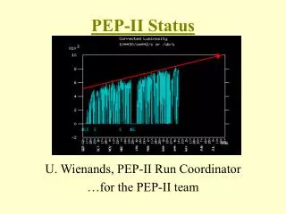
Power limited already! Same for Run 5! Linearizers will help! RF System Performance – Run 4 * Luminosity predictions assuming y, y* and n remain fixed.
This talk M Browne’s talk D Teytelman’s talk D Teytelman’s talk M Browne’s talk This talk This talk This talk This talk Courtesy: Dan Van Winkle Run 4 RF Abort Statistics Average of 3.8 Aborts/Day (2.9 Aborts/Day without non-RF events) Compared to 7/Day for Run 3
Stuck Tuners: Number of actuators with sheared pulley pins. Found carrier lead screw threads stripped (no grease!) Now re-greased ALL tuners. Slow Tuners: Readback and control positions drift slowly with time. Requiring software re-initialization. Software reset implemented re-initializes tuner positions at specific time increments. Tuner actuator system being reviewed for possible replacement: smaller motor. more compact and robust system. improved actuator mounting and control. Stuck/Slow Tuners
All 11 crowbar SCR stacks replaced again this run. Scheduled to not disrupt PEP-II operation. Leaking hermatic seals. Some stacks failed due to Si material defects. SLAC worked closely with EUPEC to overcome apparent QC problems. Faulty SCR’s repaired under warranty at EUPEC. Additional tests implemented to catch faulty units before shipment. It is now believed that the problems have been overcome. EUPEC are the only optically fired SCR vendor available at this time. SCR Stacks
Cavity Arcs • All HER stations have suffered either cavity arc or vacuum events: • VRF increased by 33% since Run 3 • Average klystron FWDP increased by 29% since Run 3 • By far the biggest cavity abort contributor has been HER 12-6 cavity A ~20 % of all HER RF aborts! • Fault files show a rapid (1-2 s) drop in cavity A accelerating field. • Much too fast for a breakdown at the RF window. • Must be happening in the cavity itself. • Installed 8 NLC-type acoustic monitors to the cavity – probe, input coupler, tuners and HOM loads did not see any pre-cursor events. • Also installed video camera looking into the movable tuner did not see any arcing events either when the station aborts. • Have not been able to correlate the station aborts with the cavity operating parameters, although appears to be somewhat sensitive to station voltage. • Looking at the raw cavity signals, have been able to localize where the problem may lie.
Similar responses! HER 12-6 Aborts (Fault File) Cavity A Probe Cavity A REVP Large reflected power signal Field Decays in 1- 2 s Cavity B Probe Cavity B REVP We shouldn’t see similar response signal in Cavity B if an arc occurs in Cavity A !?!?
No REVP change as Probe Drops out! CAVITY FIELD CANNOT BE DROPPING! HER 12-6 Aborts (Probe A) Feedback group delay
Masked cavity A probe in the LLRF system on 7/22 to ignore such a fast change in signal. Station has not aborted on such a fault since. Signal is dropping out somewhere in the probe signal path and recovers within 10 s – cavity probe, cable or coupler in LLRF rack. HER 12-6 Aborts Probe signal masked in LLRF
HER 12-6 Downtime Investigation • TDR of the probe and cable system revealed no obvious source for possible breakdown. • No signs of any breakdown features inside the cavity itself. • Internal boroscope of the installed cavity probe showed strange features! • Installed second TiN coated probe in auxiliary cavity probe location and will be used as the operational probe for Run 5. • Original probe will remain installed and used as a diagnostic tool: • Assess the effect of a solenoid around probe on breakdown frequency.
PEP-II Cavity Probe Assembly Boroscope path
Surface Disruptions Graticule Marks
HER 12-6 cavity A is a cavity received from ACCEL required rework on its nose-cone prior to installation in summer 2002. Performed rework at SLAC and RF processed quickly in the test lab. Could have been a possible source for the continuous breakdown, however no evidence observed. Nose-cone Rework Inspection Rework feature (Scotchbrite)
HER 8-3 Cavity Arcs • Latter part of Run 4 seen a number of cavity D arcs in HER 8-3. • Looks more like a real cavity arc signature. • REVP increases as (or before) the probe signal drops or saturates. • REVP increases without change in klystron signal. • Similarly masked cavity D probe signal – yet station still aborts! • Appears to be sensitive to FWDP more aborts when HER Ib increased: • Breakdown in coupler box would explain why the REVP increases before the cavity probe reacts. • Does not explain why the cavity probe signal would increase! • More than 1 problem? • More investigation required during next startup: • HOMs? – see large 7.1 GHz signal on cavity D probe and need to correlate this with other cavities in 8-3 and other stations in HER. • Longitudinal instabilities? – some of the 8-3 aborts have been associated with longitudinal beam motion – can maybe learn something from the LFB diagnostics? • LLRF anomalies? – closer monitoring of the HER 8-3 LLRF system parameters to rule out self-excitation as a possible cause.
Power Limited Klystrons Spares New RF Stations 2004 Klystron Status
Real limitation FWDP Klystron Limitations: HER 4-1, 12-1,12-6 and LER 4-3 • HER 4-1 (Philips #2) • Klystron saturation in Philips #2, power limited at ~ 850 kW. • Adjusted klystron magnetic field, output match, circulator bias and waveguide length – all to no avail! • HER 12-1 (Philips #6) • Klystron saturation in Philips #6, power limited at ~ 750 kW • Evidence of multipacting. • LER 4-3 (Philips #5) • Side-bands evident, focus adjustments did not increase power limitation. • HER 12-6 (Philips #8) • Power reduced recently in attempt to reduce cavity A arcs. • LER 4-5 (Philips #3) • Drive signal spikes in LLRF system klystron saturation. • Station phase drifts due to LLRF temperature stability.
RF System Upgrades • More RF stations: • HER10 in 2005. • LER5 in 2006. • HER11, 12 and 13 possibly beyond 2006. • Klystron Linearizer: (see Dan van Winkle’s talk) • Artificially linearizes the klystron gain. • Will improve LLRF amplitude and phase stability margins. • New Low Group Delay Woofer: (see Dmitry Teytelman’s talk) • Dedicated channel for controlling low frequency modes. • Higher feedback gains better damping. • New Longitudinal Feedback Kickers: • 2 over-damped cavity kickers installed in LER to replace LBNL designed drift-tube kickers: • Higher kicker voltage transfer efficiency. • Reduced HOM power per feedthrough (no directivity). • Incorporates new high power feedthrough design. • Integrated cooling if required. • New Comb-2 module: (see Mike Browne’s talk) • Alleviate overflow faults. • Allow for single side band (asymmetric) functionality.
PEP-II RF Station Evolution 2004 2005 2006 2006+
Conclusions For Run 4: • RF abort rate averaged 3.8/day, compared to 7/day for Run 3. • 42% of all RF aborts due to high power component problems: • Majority of which being cavity arcs, particularly in HER 12-6. • As we recovered from one major hardware problem (i.e HER 12-6) another appeared (i.e. HER 8-3). • Ongoing HVPS SCR problems addressed with EUPEC and now hopefully resolved. • Component redesigns in progress New Comb-2 module and tuner actuators. • Beam currents increased by 41% in HER and 63% in LER. For Run 5: • Will have 2 operational spare Philips klystrons, plus a repaired SLAC tube by early 2005. • More SLAC klystrons being built to replace older, power limited Philips tubes. • Currently power limited in the HER, particularly the Philips klystrons linearizer system hoped to help! • New LER RF station and LFB kickers >30% larger LER beam current. • New (split) HER RF station nominal 13% increase in HER beam current. • LLRF system improvements underway to improve system stability and reliability.
Acknowledgements • Must go to all members of the PEP-II RF Systems Taskforce, comprising people from many SLAC departments: • ARD-A LFB Systems • ESD LLRF and Software Systems • Klystron High Power RF and TFB Systems • PCD HVPS Systems