Download
1 / 19
190 likes | 339 Views
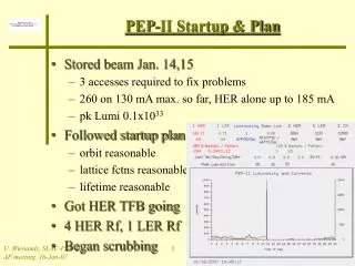
PEP II Transverse Feedback System. Ron Akre William Colocho Anatoly Krasnykh Vojtech Pacak Dmitry Teytelman Uli Wienands Andrew Young MAC October 26, 2006. PEP II Transverse Feedback System.

E N D
PEP II Transverse Feedback System Ron Akre William Colocho Anatoly Krasnykh Vojtech Pacak Dmitry Teytelman Uli Wienands Andrew Young MAC October 26, 2006 PEP TFB R.Akre
PEP II Transverse Feedback System The PEP TFB system takes the vector sum of 2 BPMs, delays the signal by the remainder of 1 turn and delivers a kick to the beam the next time around. Two stripline kickers, one for X and one for Y, are used. PEP TFB R.Akre
PEP II TFB Highlights for Run 5b Fine tuning of receiver chassis to reduce phase transient New 2 channel GaGe card collects data on Sum Signal New LBNL Digital Delay lines installed in HER X and Y and LER Y Lost only 1 power amp this run! LBNL assistance with transfer function measurements Fire PEP TFB R.Akre
PEP II Transverse Feedback SystemRun 5 Hardware Problems • Run 5B – 4 Hardware Problems • LER X Digital delay blown fuze • GaGe board computer hard drive storage used up • GaGe board failed • LER X - Kicker Cables, Filter cable, Power Amp • Run 5A - 18 Log Entries associated with hardware problems • 16 Power Amp Problems • 14 transistors • 5 regulator boards • 1 High Power Filter Blown: LER Y- • 1 Failed BPM Attenuators: LER 2C PEP TFB R.Akre
Use These Phase Shifters to Remove Phase Transient PEP II TFB Receiver PHASE TRANSIENT PEP TFB R.Akre
PEP II TFB Digital Delays Principal Investigators: Walter Barry and John Byrd Alex Chin, Larry Doolittle, Alex Ratti, Jonah Weber Phase 1: 2 - 12 bit ADC to clock data into FPGA at 238MHz Two tap filter with 1 turn delay plus variable delay 238MHz DAC with differential output Programmable through COM port. Completed – Installed in LER Y August 2005 Installed in HER X and Y December 2005 Phase 2: Record 16MS, 70mS, of data to external memory Three trigger modes Grow/ Damp Measurements Fault File Data Software trigger to capture data during running System Operational but noise levels prevent PEP deployment – MoA with LBNL in process to get assistance in looking at noise levels • Lawrence Berkeley Laboratory Power Amplifier Overhead and Reliability has Greatly Improved!!! PEP TFB R.Akre
Power Amplifiers • We only lost one power amplifier during run 5B – likely during by 4 bunch pattern operation with possible bad filter cable. No power transistors failed! • During run 5A we lost 14 output power transistors. • Before two tap delays, orbit offsets and phase transients cause the amplifiers to run close to saturation. The new digital delay two tap filters eliminate orbit offsets and greatly reduce power requirements in the amplifers. • Filters • No filter failures during run 5B. Mechanical cable connector failure to filter load. PEP II TFB Power Amplifiers and Filters PEP TFB R.Akre
Added New 2 channel GaGe card PEP II TFB Data Acquisition System Files are stored in central NFS space Compiled MatLab routines for analysis of data sets are run from a GUI PEP TFB R.Akre
PEP II TFB Data Acquisition SystemAnalysis Software Compiled MatLab Software Run from GUI Now includes X and Y Sum Channels Display All Data Display Selected Data Plot RMS FFT Plot Modes Plot Mode Phase Plot Mode Growth Fit High Resolution FFT High Resolution FFT 2 Plot Spectrogram W. Colocho, V. Pacak PEP TFB R.Akre
X Y 12-08-05 21:17 ~2200mA LER X LER CURRENT Y PEP TFB R.Akre
Her Y 1496mA Grow/Damp HER Y Grow/Damp Measurements PEP TFB R.Akre
Loss of Directivity: HOM Simulations (single bunch) Beam Direction PEP TFB R.Akre
PEP II TFB Comments and Concerns for Higher Current Running • Feedback Gain and Output Power • Further grow / damp measurements in both HER and LER. • LBNL two tap filters have shown large increases in system gain and amplifier reliability • Systems seem to be well damped – even during arcing conditions • Filters are currently working well – Need to check cables • Kickers • LER X Kicker has problem with electrode support. May not make it through next run in existing condition. • Even with cable fire 7/16DIN Feed-through connectors did not fail. • As the bunch length shortens higher frequencies of beam induced power will need to be directed to proper loads. • Measurements of beam induced power from kicker to amplifiers need to be done. • BPMs • Need to look closely at X- and possibly Y- offset. PEP TFB R.Akre
PEP II TFB Near Term Run 6 Tasks • Set up MoA with LBNL to assist with noise, grow/damp, and transfer function measurements • Measure power reflected to amplifier from kicker • Especially LER X- and Y- compared to X+ and Y+ • Resolve LER X 11mm offset discrepancy • Grow / damp measurements both planes of both rings • Transfer function measurements in both rings • Install 2 tap filter in LER X • Replace LER X Kicker Cables with all 7/8 inch Heliax PEP TFB R.Akre
End of Talk PEP TFB R.Akre
LER 3051 and 3031 BPM-to-Receiver cables with 6dB attenuators 3051 BPM 3031 BPM Electrical length of all four 3051 BPM channels is the same. Electrical length of 3031 BPM is the same with ~50 psec tolerance Amplitudes of A (red), B (yellow), and C (green) 3051 BPM signals are practically the same. Amplitude of D (blue) signal is ~5% less. Amplitudes of all four 3031 BPM channels is practically the same. Anatoly Krasnykh PEP TFB R.Akre
Result of LER Receiver Cold Tests x2 x1 y1 y2 Receiver #1 Receiver #2 Amplitudes of output receiver signals in X and Y channels are nearly zero if all four inputs have the equal amplitudes. Amplitudes of error signals are shown when receivers are activated by one channel. Both LER receivers are fine. Anatoly Krasnykh PEP TFB R.Akre
PEP II TFB Kickers Uli Wienands, Anatoly Krasnykh, Artem Kulikov, Jay Langton, David Kharakh Many Others New kickers with moly electrodes, redesigned coax to stripline transition, and 7/16 DIN connectors have been installed in LER. LER X KickerBefore Installation LER X Kicker After Run 5B PEP TFB R.Akre
Transfer Function Measurements Attached are the amplitudes the of transfer functions recorded from the photos for the first hundred sidebands. First is vertical, second is horizontal. Lots of caveats in interpreting the data: very uneven bunch patterns, etc. However, the signal strength is very good and we should be able to measure the broadband open loop response of the entire TFB at low current. This will tell us if the system is operating as it should (in the linear mode). As we raise the current, I hope we can identify any impedances which will modify the transfer function. The combination of this data should allow us to predict the linear performance of the system at high current. The final phase would be to monitor the closed loop response to see what we can find out. John Byrd, Stefano De Santis LBNL PEP TFB R.Akre