Download
1 / 10
100 likes | 327 Views
FIGURE 21–1 A gasoline direct-injection system injects fuel under high pressure directly into the combustion chamber. FIGURE 21–2 An engine equipped with a gasoline direct injection (GDI) sometimes requires a NO X catalyst to meet exhaust emission standards.

E N D
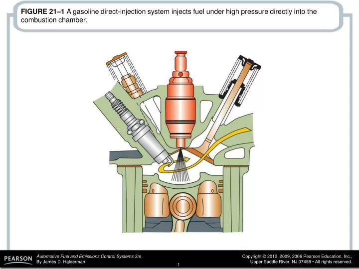
FIGURE 21–1 A gasoline direct-injection system injects fuel under high pressure directly into the combustion chamber.
FIGURE 21–2 An engine equipped with a gasoline direct injection (GDI) sometimes requires a NOX catalyst to meet exhaust emission standards.
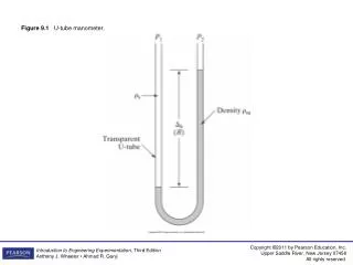
FIGURE 21–3 A typical directinjection system uses two pumps—one low-pressure electric pump in the fuel tank and the other a high-pressure pump driven by the camshaft. The high pressure fuel system operates at a pressure as low as 500 PSI during light load conditions and as high as 2,900 PSI under heavy loads.
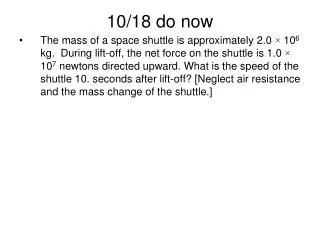
FIGURE 21–4 A typical camshaft-driven high-pressure pump used to increase fuel pressure to 2,000 PSI or higher.
FIGURE 21–5 A gasoline direct-injection (GDI) fuel rail and pump assembly with the electric pressure control valve.
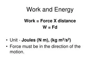
FIGURE 21–6 In this design, the fuel injector is at the top of the cylinder and sprays fuel into the cavity of the piston.
FIGURE 21–7 The side injector combines with the shape of the piston to create a swirl as the piston moves up on the compression stroke.
FIGURE 21–8 The piston creates a tumbling force as the piston moves upward.
FIGURE 21–9 Notice that there are conditions when the port fuel-injector located in the intake manifold, and the gasoline direct injector, located in the cylinder both operate to provide the proper air–fuel mixture.
FIGURE 21–10 There may become a driveability issue because the gasoline direct-injection injector is exposed to combustion carbon and fuel residue.