Download
1 / 10
100 likes | 109 Views
The ILC, CALICE and the ECAL. Paul Dauncey Imperial College London. MAPS work is part of CALICE. CALICE collaboration Looking at electromagnetic ( ECAL ) and hadronic (HCAL) calorimetry for the International Linear Collider ( ILC )

E N D
The ILC, CALICE and the ECAL Paul Dauncey Imperial College London Paul Dauncey
MAPS work is part of CALICE • CALICE collaboration • Looking at electromagnetic (ECAL) and hadronic (HCAL) calorimetry for the International Linear Collider (ILC) • ILC is likely to be the next big HEP machine after the LHC • Electron-positron collider at ECM at least 500 GeV • As yet unapproved and unfunded; need global collaboration as very expensive (several billion £) • Timescale also uncertain but working assumption is running in 2016 • Detector Technical Design Reviews have been scheduled for 2009 • 2009 is the target date for proving new technologies for detectors • This sets the timescale for our MAPS work Paul Dauncey
5 Hz / ILC operation and readout TESLA 500GeV 2820 bunches // / 1ms 199 ms Buffer data Triggerless data readout • Exact beam timing parameters not defined; assume worst case • Beam collision rate within train ~ 7MHz, i.e. 150ns between collisions • Number of collisions within train ~ 14000 bunches, i.e. train is 2ms long • Train rate ~10Hz, i.e. 98ms between trains; 2% duty cycle • Detectors will not have an hardware trigger • Data from whole bunch train buffered on-detector for 2ms • All data read out in 98ms before next bunch train • All data from one bunch train sent to PC farm; event data picked out in time slices and reconstructed offline Paul Dauncey
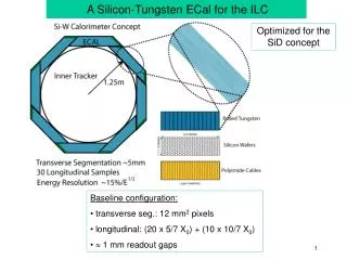
CALICE baseline ECAL • CALICE has a baseline ECAL design • Sampling calorimeter, alternating thick conversion layers (tungsten) and thin measurement layers (silicon) • Around 2m radius, 4m long, 30 layers tungsten and silicon • Silicon sensor detectors in baseline are diode pads; detect charged particles by electron-hole pair creation • Pad readout is analogue signal; digitised by Very Front End (VFE) ASIC mounted next to sensor • Pad size between 1×1 and 0.5×0.5 cm2; total number of pads around 20-80M • Mechanical structure • Half of tungsten sheets embedded in carbon fibre structure • Other half of tungsten sandwiched between two PCBs each holding one layer of silicon detector wafers • Whole sandwich inserted into slots in carbon fibre structure • Sensitive silicon layers are on PCBs ~1.5m long (!) ×30cm wide Paul Dauncey
(Close to) baseline design Silicon wafers ~ 10×10cm2 Paul Dauncey
MAPS concept • Try to retain as much as possible of CALICE baseline design • Less work to do to prove other parts of design, e.g. mechanics, long PCB • Conceptually aim to swap diode pad sensors for MAPS sensors • Aim to be competitive in terms of granularity, efficiency, power and cost • MAPS sensors would have much smaller pixels, ~ 50×50mm2 • Probability of more than one particle small; allows binary readout • Discriminate pixel signal for every collision within a train • Gives binary value for each pixel for each collision • Record collision numbers (timestamps) each time above threshold • Timestamps can have values up to 14000, i.e. 14 bits • Store result in memory on sensor during train up to some maximum number of timestamps • Read out all timestamps in dead time before next train • Ensure total readout completed before next train Paul Dauncey
Critical parameters for MAPS • Pixel size • Significant probability of two particle per pixel gives non-linear response • Charge diffusion leads to crosstalk; worse for smaller pixels • Thickness of gap between tungsten layers • This must be minimised to prevent particles spreading out between layers • Silicon wafer cost • ECAL cost dominated by silicon wafers • Total silicon area is around 2000m2 so huge amount is needed • For diode pads, high resistivity silicon must be used • MAPS are CMOS sensors so standard silicon and so (we hope) cheaper • Data volume, noise and efficiency • Data rate of pixels dominated by noise; must not fill sensor memory • High threshold desirable but only possible if good S/N ~ 10 • Threshold value must be carefully adjusted (and hence be adjustable) Paul Dauncey
Pixel size • EM shower core density at 500GeV is ~100/mm • Pixels must be < 100100mm2; working number is 5050mm2 • Have to be able to fit pixel circuit into area • 2525mm2 may not be large enough • Preliminary simulation studies show improvement over baseline • Diode pads measure energy deposited; depends on angle, Landau, velocity • Binary pixels measure number of particles; better estimate of shower energy • Simulation does not include crosstalk yet; may be limit on smaller pixels Two-particle separation Paul Dauncey
Power issues • Thickness of tungsten layer gap dominates shower spread • Implies no protrusions above wafers; i.e. no wirebonds • Baseline ECAL has diode pads conductively glued directly to PCB Cooling VFE chip Si Wafers PCB Tungsten 8.5mm 6.4mm thick 4.0mm thick • Power and cooling become critical issues; how to get heat out? • MAPS must be comparable to baseline to be considered seriously • VFE chip will dominate; aiming for ~10mW/channel ~ 10mW/cm2 • Averages to ~ 1mW/mm2 if only powered on during train Paul Dauncey
Summary of MAPS requirements • Low power, comparable to 1mW/mm2 average • Low noise and high S/N, so dark noise rate 105 or better • Sufficient buffering to not fill memories during bunch train; 10 10 probability of overflow • Low probability of multiple particles per pixel and low crosstalk; total 5% • Good efficiency and small dead areas; total 10% lost of particles • Adjustable threshold Paul Dauncey