Download
1 / 28
590 likes | 1.68k Views
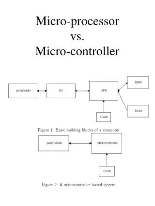
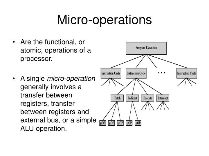
Micro-operations. Are the functional, or atomic, operations of a processor. A single micro-operation generally involves a transfer between registers, transfer between registers and external bus, or a simple ALU operation. Micro-operations and the Clock.

E N D
Micro-operations • Are the functional, or atomic, operations of a processor. • A single micro-operation generally involves a transfer between registers, transfer between registers and external bus, or a simple ALU operation.
Micro-operations and the Clock • Each clock pulse defines a time unit, which are of equal duration. • Micro-operations are performed within this time unit. • If multiple micro-operations do not interfere with one another then grouping of micro-operations can be performed within one time unit. • Grouping can be performed as long as; • Proper sequence of events are followed • PC MAR must be done first in order for MEMORY MDR • Conflicts are avoided • MEMORY MDR can not be in the same time unit as MDR IR
The Fetch Cycle • Consists of three time units and four micro-operations. • Each micro-operation involves the movement of data into or out of a register.
The Indirect Cycle • Occurs if the instruction specifies an indirect address. • Consists of three time unit and three micro-operations. • Data is transferred to the MAR from the IR, which is used to fetch the address of the operand, the IR is then updated from MDR so it contains a direct address rather than indirect.
The Interrupt Cycle • Occurs if any enabled interrupts have occurred at the completion of the execute cycle. • The contents of the PC are transferred to the MDR, so that they can be saved for return from the interrupt. • MAR is loaded with the address at which the contents of the PC are to be saved • PC is loaded with the address at the start of the interrupt routine. • Final step is to store the MDR into MEMORY.
The Execute Cycle • Execute cycle is not as predictable as other cycles (fetch, indirect, or interrupt). • Number of time units and micro-operations varies for every execution cycle. Example; ADD R1, X • The following execute cycle adds the contents of the location X to register R1.
Instruction Cycle • Each phase decomposed into sequence of elementary micro-operations (fetch, indirect, and interrupt cycles) • Execute cycle • One sequence of micro-operations for each opcode • Need to tie sequences of micro-operations together • Assume new 2-bit register • Instruction cycle code (ICC) designates which part of cycle the processor is in: 00: Fetch 10: Execute 01: Indirect 11: Interrupt
Functional Requirements • Define basic elements of processor • Describe micro-operations processor performs • Determine functions control unit must perform Basic Elements of the Processor ALU External data paths Control Unit Registers Internal data paths
Types of Micro-operation • Transfer data between registers • Transfer data from register to external • Transfer data from external to register • Perform arithmetic or logical operations Functions of Control Unit • Sequencing Causes the processor to step through a series of micro-operations • Execution Causes the performance of each micro-operation • This is done using Control Signals
Control Signals - Input • Clock • One micro-instruction (or set of simultaneous micro instructions) per clock pulse. • Instruction register • Op-code of the current instruction • Determines which micro-instructions are performed • Flags • Determines the status of the processor • Results of previous ALU operations • Control Signals from control bus • Interrupts • Acknowledgements
Control Signals - Output • Control Signals within the processor • Cause data movement • Activate specific ALU functions • Control Signals to control bus • To memory • To I/O modules
PROCESSOR ORGANIZATION • Organization is how features are implemented • Control signals, interfaces, memory technology. • e.g. Is there a hardware multiply unit or is it done by repeated addition
Internal Organization • Usually a single internal bus • Using single bus simplifies & saves space • Gates control movement of data onto and off the bus • Control signals control data transfer to and from external systems bus • Temporary registers needed for proper operation of ALU
Fetch Sequence (symbolic) • t1: MAR <- (IRaddress) address field of IR • t2: MBR <- (memory) • t3: Y <- (MBR) • t4: Z <- (AC) + (Y) • t5: AC <- (Z)
CPU Clock • Clock • Repetitive sequence of pulses • Useful for measuring duration of micro-ops • Must be long enough to allow signal propagation • Different control signals at different times within instruction cycle • Need a counter with different control signals for t1, t2 etc.
Hardwired Implementation • Control unit inputs • Flags and control bus • Each bit means something • Instruction register • Op-code causes different control signals for each different instruction • Decoder takes encoded input and produces single output • n binary inputs and 2n outputs
Hardwired Logic • Logic Gates Hardwired Internally • Functions predefined • Truth Tables • Boolean Logic used to define timing • Connect Instructions • Unique logic for each set of op-codes
Problems With Hard Wired Designs • Complex sequencing & micro-operation logic • Difficult to design and test • Inflexible design • Difficult to add new instructions
URL Reference • http://en.wikipedia.org/wiki/Micro-operation • http://www.vocw.edu.vn/content/m10780/latest/ • http://en.wikipedia.org/wiki/Control_unit
Review Questions • A single micro-operation generally involves? • A transfer between registers, transfer between a register and an external bus, or a simple ALU operation. • What is the main purpose of grouping micro-operations together? • To save time.
What are the basic tasks of a control unit? • Sequencing & Execution • What are the inputs of a control unit? • Clock, IR, Flags, and control signals from control bus. • What is the control signal? • What is a hardwired Implementation? • Each intruction cycle is divided from 1 to 5 machince cycle; each machine cycle into turn is divided any where from 3 to 5 states. • The y register is used as temporary storage for the ALU and the X register is used a tempory output storage.