Download
1 / 23
240 likes | 391 Views
Performance of CMS Cathode Strip Chambers. Andrey Korytov (for CMS Collaboration). Compact Muon Solenoidal Detector (CMS). Endcap Muon System is based on Cathode Strip Chambers (CSCs) 4 stations (disks of CSCs) in each endcap 6 sensitive planes per CSC 468 CSCs with total

E N D
Performance of CMS • Cathode Strip Chambers Andrey Korytov (for CMS Collaboration) Andrey Korytov, University of Florida IEEE Nuclear Science Symposium, Honolulu, 31 October 2007 1
Compact Muon Solenoidal Detector (CMS) • Endcap Muon System • is based on Cathode • Strip Chambers (CSCs) • 4 stations (disks of CSCs) • in each endcap • 6 sensitive planes per CSC • 468 CSCs with total • sensitive area >5000 m2 • pseudorapidity coverage • 0.9<|h|<2.4 • ~500K readout channels • Provides: • - muon trigger • muon identification and • precise measurements Andrey Korytov, University of Florida IEEE Nuclear Science Symposium, Honolulu, 31 October 2007 2
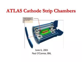
One of 8 endcap stations Andrey Korytov, University of Florida IEEE Nuclear Science Symposium, Honolulu, 31 October 2007 3
What’s new • Performance of CMS CSCs was extensively studied over the last 10 years during R&D and production: • cosmic ray muons, muon beams, high irradiation rate conditions, etc. • BUT one chamber at a time (often a small fraction of a chamber area) in lab conditions • In this talk, we present the first results obtained with: • 36 CSCs operated in situ as one system • 400 m2 of sensitive planes • 8% of the entire CMS CSC system • cosmic ray muons • Presented: • Track Segment finding efficiency (Level 1 Trigger) • Fast Precision Coordinate reconstruction (High Level Trigger) Andrey Korytov, University of Florida IEEE Nuclear Science Symposium, Honolulu, 31 October 2007 4
ME+4 ME+3 ME+2 ME+1 60 CMS Magnet Test and Cosmic Challenge • Fall 2006 • CSC scope • 60-sector of one of the two endcaps • 36 chambers, ~8% of all Andrey Korytov, University of Florida IEEE Nuclear Science Symposium, Honolulu, 31 October 2007 5
CSC design and readout • Large chambers • Wires groups: 5 cm wide • Cathode strips: 8-16 mm wide wire-group hits every 25 ns same information for trigger/offline 3.3 m Level-1 Trigger: half-strip hits every 25 ns HLT*/offline: 12-bit digitization every 50 ns *HLT – High Level Trigger Andrey Korytov, University of Florida IEEE Nuclear Science Symposium, Honolulu, 31 October 2007 6
Track Segments for L1 Trigger • 1D Track Segments • (pattern recognition is implemented in firmware) • wire-group hits in six planes half-strip hits in six planes • 2D Track Segments • are combinatorial combinations of all 1D wire- and strip-segments • Efficiency requirement >99% Andrey Korytov, University of Florida IEEE Nuclear Science Symposium, Honolulu, 31 October 2007 7
Digitized strip signals for HLT/offline strip 6 signal strip 5 signal strip 4 signal • Strip signals are sampled • and digitized every 50 ns • HLT requirements: • Resolution: <0.5 mm per segment • CPU: ~ ms per segment • (time budget for entire HLT is 40 ms) • Offline requirements: • Resolution: 150 mm per segment strip 3 signal strip 2 signal strip 1 signal Andrey Korytov, University of Florida IEEE Nuclear Science Symposium, Honolulu, 31 October 2007 8
Track Segment Efficiency measurement • Magnetic field 0 T • Trigger is based on ME1 and ME3 stations only • ME2 station is also in readout, but not in the trigger • Only one Track Segment in ME1 and ME3 () • ME1+ME3 provide prediction in ME2 () • Residual = Segment in ME2 () – Prediction () Andrey Korytov, University of Florida IEEE Nuclear Science Symposium, Honolulu, 31 October 2007 9
Predicted Track Segment in ME2/2 CSCs Predicted hits that were missed in ME2/2 Blue sub-trapezoids – nominal fiducial area of “guaranteed’ full efficiency Coordinates of all predicted hits in ME2/2 Red trapezoid – chamber outline Dashed lines – “semi-dead” areas separating 5 independent plane sections Andrey Korytov, University of Florida IEEE Nuclear Science Symposium, Honolulu, 31 October 2007 10
Track Finding Efficiency of ME2/2 CSCs Average efficiency 99.93±0.03% NO CUTS Red points – measurements Blue line – expectation taking into account “semi-dead” areas separating independent wire plane sections ONLY FIDUCIAL AREA OF FULL EFFICIENCY Red points – measurements Andrey Korytov, University of Florida IEEE Nuclear Science Symposium, Honolulu, 31 October 2007 11
Sagitta based on found track segments Histogram—measured residuals Line—expected residuals, simple calculations based on cosmic ray muon momentum spectrum Scatter plot of sagitta measurements sdY is larger due to courser Y-coordinate measurements (wire groups vs half-strips) Average offset is due to iron disk misalignment during MTCC—confirmed by geodesic survey Andrey Korytov, University of Florida IEEE Nuclear Science Symposium, Honolulu, 31 October 2007 12
Fast algorithm for hit/segment reconstruction at HLT • Reuse L1 Track Segments: • can be done due to their very high efficiency and good (few mm) pointing • by design, if L1 Track Segment is not found, no data are read out from that chamber by DAQ • Using digitized strip signals, find x-coordinates • drop calibrations (gain, pedestals, x-talks, noise correlation matrix, plane mis-alignment): • can be done due to high uniformity of the system • no database access is needed • build x-coordinate as a function of digitized signals • no iterative fitting • Using six x-coordinates, find segment coordinates • linear procedure (no iterations) • prune up to two outliers • CPU time performance: 0.45 ms per segment (Intel 2.8 GHz P4) Andrey Korytov, University of Florida IEEE Nuclear Science Symposium, Honolulu, 31 October 2007 13
Q2 Q3 Q1 charge pedestal time Fast x-coordinate (1) • Use first two time samples to build pedestals dynamically (to reduce noise, average as new events come in) • Add three samples with signal (max ± 1) • Use an old method of ratio of charges to get a first approximation for a local coordinate in strip width units Qcenter Qright Qleft strips Andrey Korytov, University of Florida IEEE Nuclear Science Symposium, Honolulu, 31 October 2007 14
Fast x-coordinate (2) • Correct for expected non-linearity using the Gatti shape of the induced charge (correction is a simple strip width-dependent function) • Check occupancy for reconstructed coordinate. It is not flat indicating there is a remaining non-linearity. • Fit the occupancy and reconstruct empirical correction (which happens to be almost strip-width independent) Andrey Korytov, University of Florida IEEE Nuclear Science Symposium, Honolulu, 31 October 2007 15
Plane 1 Plane 2 Plane 3 Plane 4 Plane 5 Plane 6 Residuals in test (3rd) plane Plane 3 is not used in the track segment fit Residual(3) = xmeas(3) – xfit(3) strip center strip edge Andrey Korytov, University of Florida IEEE Nuclear Science Symposium, Honolulu, 31 October 2007 16
Extrapolating to the full track segment • There was not a precise reference prediction for a track segment in MTCC. Hence, we just extrapolate single plane resolutions to the overall six-plane resolution • CSC six-plane resolution is ~150 mm • by far exceeds the HLT requirement of <0.5 mm • actually, very close to design spec for the ultimate offline resolution HLT requirement Andrey Korytov, University of Florida IEEE Nuclear Science Symposium, Honolulu, 31 October 2007 17
Summary • Trigger performance of CMS CSCs evaluated • with cosmic rays • using 36 CSCs operated in situ as one system • 2d Track Segments for Level-1 trigger: • efficiency 99.9% (required 99%) • sagitta residuals are consistent with m.s. of cosmic ray muons (~3 mm) • decision time 800 ns (firmware, by design) • Track Segments for High Level Trigger • localization per chamber ~150 mm (required 0.5 mm) • robust, no losses in efficiency (by algorithm design) • decision time 0.5 ms (software, required ~ ms) Andrey Korytov, University of Florida IEEE Nuclear Science Symposium, Honolulu, 31 October 2007 18
Backup slides Andrey Korytov, University of Florida IEEE Nuclear Science Symposium, Honolulu, 31 October 2007 19
CSC Design Parameters • Overall size: 3.3 x 1.5/0.8 m2 (trapezoidal) • 7 panels form 6 gas gaps of 9.5 mm • Anode-Cathode: h=4.75 mm • Anode wires: d=50 mm, gold-plated tungsten • Wire spacing:s=3.2 mm pitch • Wire tension:T=250 g (60% elastic limit) • Readout group:5 to 16 wires (1.5-5 cm) • Cathode strips: w=8-16 mm wide (one side) • Gas: Ar+CO2+CF4=40+50+10 • Nominal HV: 3.6 kV • Gas Gain: 105 Andrey Korytov, University of Florida IEEE Nuclear Science Symposium, Honolulu, 31 October 2007 20
Singles Rate Curve dark count rate ~ 0.04 Hz/cm2 Andrey Korytov, University of Florida IEEE Nuclear Science Symposium, Honolulu, 31 October 2007 21
CSC aging test results • Setup: • Full size production chamber • Prototype of closed-loop gas system • nominal gas flow 1 V0/day, 10% refreshed • Large area irradiation • 4 layers x 1 m2, or 1000 m of wires • Rate = 100 times the LHC rate • 1 mo = 10 LHC yrs • Results: • 50 LHC years of irradiation (0.3 C/cm) • No significant changes in performance: • gas gain remained constant • dark current remained < 100 nA (no radiation induced currents a la Malter effect) • singles rate curve did not change • slight decrease of resistance between strips • Opening of chamber revealed: • no debris on wires • thin layer of deposits on cathode (stinky!)—no effect on performance Anode wire after aging tests Andrey Korytov, University of Florida IEEE Nuclear Science Symposium, Honolulu, 31 October 2007 22
CSC Production Sites • CSC Assembly (Fermilab, PNPI-St.Petersburg, IHEP-Beijing, JINR-Dubna) • On-CSC electronics (Universities: Ohio State, UCLA, Carnegie-Mellon, Wisconsin) • Final Assembly and System Tests (Univ. of Florida, UCLA, PNPI, IHEP, JINR) • Pre-installation tests and final commissioning (CERN) Andrey Korytov, University of Florida IEEE Nuclear Science Symposium, Honolulu, 31 October 2007 23