Download

1 / 21
210 likes | 308 Views
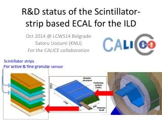
Performance of new strip scintillator. Minseok Park . Jungeun Lee, Jaeyun Choi , Kyungpook National University . Contents. Ⅰ. Introduction Ⅱ. Experimental Setup Ⅲ. Result of Measurement Ⅳ. Conclusion. Configurations. The strip used to FNAL prototype

E N D
Performance of new strip scintillator Minseok Park Jungeun Lee, JaeyunChoi, Kyungpook National University
Contents Ⅰ. Introduction Ⅱ. Experimental Setup Ⅲ. Result of Measurement Ⅳ. Conclusion
Configurations The strip used to FNAL prototype 45mm X 10mm X 3mm (fiber, silver film cover) Strip 1. (fiber) 45mm X 5mm X 3mm Recently produced strips : width all 5mm Strip 2. (direct readout) 45mm X 5mm X 3mm Strip 3. (direct readout) 45mm X 5mm X 2mm Strip 4 used to DESY prototype 45mm X 10mm X 3mm (fiber) [White paint cover]
5 Types of scintillators 10mm 5mm Strip 2 Strip 3 Strip 1 DESY version Strip FNAL version Strip
Ⅱ. Experimental setup VME ADC Thermostat chamber Gate IN Trigger logic Scanning stage Trigger PMT PC MPPC Sig IN Beta-ray Source (137Cs) Readout circuit Beta ray Signal Bias voltage Automated 2-D scanning system Voltage source Collimated b - ray Scanner controller MPPC
Experimental Setup(trigger) AMP Target scintillator MPPC Trigger scintillator and Trigger logic process
Target scintillator MPPC Scintillator testing with Motor Control System Trigger scintillator
Analysis procedure 1-d projection part is just this part. • For the data collected at each point • Take ADC distribution with beta-ray signal • Cut the pedestal part, take average of signal region • The average shows strip response at this point • Repeat same thing for all the point ped Take average of This region signal Cut here !
Ⅲ. Result of Measurement 1) FNAL version vs DESY version Silver film white paint FNAL version Strip DESY version Strip 4 The Comparison of the covering materials while other conditions are same
1) FNAL version vs DESY version FNAL version with Silver cover DESY version with white paint Standard result As reference 990-860 ~130 Light yield is slightly lower but uniformity Is better. 760-740 ~20
2) FNAL version vs 5mm Width strip 5mm 10mm FNAL version Strip 10mm Strip1 5mm (fiber) The Comparison of the width while other conditions are same
2) FNAL version vs5mm Width strip FNAL version width 10mm Strip 1 width 5mm Standard result As reference 990-860 ~130 Light yield is much lower but uniformity Is better. 500-480 ~20
3) With silver cover vs Without cover(5mm) The Comparison of the Existence of silver cover while other conditions are same
3) With silver cover vs Without silver cover(5mm) Strip 1 With silver cover Strip1 Without silver cover 500-480 ~20 350-330 ~20 The strip1 with silver cover gets higher Light yield. And uniformity is same.
4) With fiber vs Direct readout (5mm) Strip1 (fiber) Strip2 (Direct readout) Comparison of the existence of fiber Compare strip with fiber and direct readout while other conditions are same
4) With fiber vs Direct readout(5mm) Strip 1 With fiber Strip 2 Direct readout 500-470 ~30 930-870 ~60 The strip1 with fiber gets lower Light yield than strip2 But uniformity is better.
5) Thickness : 3mm vs 2mm(Direct readout) Strip2 Thickness : 3mm Strip3 Thickness : 2mm Comparison of the Thickness of strip while other conditions are same
5) Thickness : 3mm vs 2mm(Direct readout) Strip 3 Thickness 2mm Strip 2 Thickness 3mm 930-880 ~50 950-830 ~120 The strip3(2mm) gets little higher Light yield than strip2(3mm). But uniformity is worse.
Ⅳ. Conclusion • FNAL version(silver cover) vs DESY version(white paint) • Light yield : FNAL version > DESY version • Uniformity : FNAL version < DESY version • FNAL version(10mm width) vs Strip1 (5mm width) • Light yield : FNAL version > 5mm Width strip • Uniformity : FNAL version < 5mm Width strip 5mm width strip is not good for getting higher light signal But, Its uniformity is better than FNAL version.
Ⅳ. Conclusion • With silver cover vs Without silver cover (5mm) • Light yield : With silver cover > Without silver cover • Uniformity : With silver cover ~ Without silver cover • With fiber vs Direct readout (5mm) • Light yield : With fiber < Direct readout • Uniformity : With fiber > Direct readout • Thickness : 3mm vs 2mm(Direct readout) • Light yield : Thickness : 3mm < Thickness : 2mm • Uniformity : Thickness : 3mm < Thickness : 2mm
Plan • Polishing the strip • Silver painting • Checking the strip clearly by using the microscope • Improving the manufacturing system * Long term plan • Making more stable system • Developing optical simulation Reflector Photo sensor