Download
1 / 33
330 likes | 562 Views
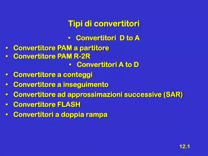
Tipi di convertitori Convertitori D to A Convertitore PAM a partitore Convertitore PAM R-2R Convertitori A to D Convertitore a conteggi Convertitore a inseguimento Convertitore ad approssimazioni successive (SAR) Convertitore FLASH Convertitori a doppia rampa. Richiami.

E N D
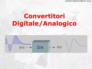
Tipi di convertitori • Convertitori D to A • Convertitore PAM a partitore • Convertitore PAM R-2R • Convertitori A to D • Convertitore a conteggi • Convertitore a inseguimento • Convertitore ad approssimazioni successive (SAR) • Convertitore FLASH • Convertitori a doppia rampa
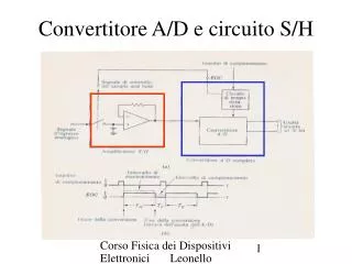
Richiami • Circuito Sampling- Hold • Pulse Code Modulation (PCM) • Pulse Amplitude Modulation (PAM) • Pulse width Modulation (PWM)
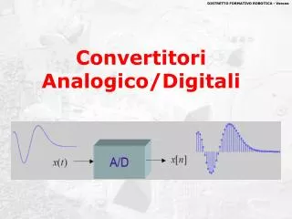
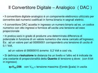
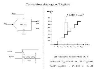
Convertitore D to A • Notazione posizionale ( N = 4) • Può rappresentare una tensione • Si può realizzare utilizzando un sommatore analogico realizzato con amplificatore operazionale
Sommatore R0 • Metodo del CCV R1 V1 R2 - V2 Vu +
Convertitore - VR 1 k a3 1 K 2 k a2 4k - a1 Vu + 8 k a0 0
Osservazioni • Per N = 10 la resistenza più grossa vale 1024 volte la più piccola • Affinché non si “mascheri” con la resistenza più grande quella più piccola ci vuole una elevata precisione (per N = 10 Rmax = 1024 Rmin ± 0.05 % !!!) • Nei circuiti integrati si riesce a fare due resistenze uguali con elevata precisione • Il valore assoluto non è affidabile • Le resistenze di valore elevato si realizzano male
Buffer • In base al CCV • Resistenza d’ingresso alta • Resistenza d’uscita bassa - out + Vin
Convertitore D/A a reticolo R ÷2R VX0 VX1 VX2 VX3 VU - A R B R C R D + 2R 2R 2R 2R 2R 2R a0 a1 a2 a3 0 VR
Resistenza vista VX0 VX1 VX2 VX3 A R B R C R D Vu 2R 2R 2R 2R 2R 2R Rv=R Rv=R Rv=R Rv=R
VU (1) VR VX0 VX1 VX2 2R A R B R C R D Vu=VR/3 2R 2R 2R 2R 2R 2R 2R
VU (2) VR VX0 VX1 VX3 2R A R B R R D Vu C 2R 2R 2R 2R 2R
2R VU (3) VR VX0 2R VX2 VX3 A R R C R D Vu B 2R 2R 2R 2R
2R 2R VU (4) VR VX1 VX2 VX3 2R R R C R B D Vu A 2R 2R 2R
Osservazioni • Da ogni nodo (A, B, C, D) guardando a destra e a sinistra si vede 2R (esempio: da A vs Sx 2R, vs Dx 2R||2R+R = 2R) • La Vxn con solo il bit n attivo vale • VU(1000) = VR/3, VU(0100) = VR/6, VU(0010) = VR/12, VU(0001) = VR/24 • La rete è lineare, quindi si può usare il principio di sovrapposizione degli effetti
Note • Per avere VUmax =15 V deve essere VR =24 V • Se VR si considera un ingresso si ottiene un attenuatore programmabile • Si può vedere anche come un MOLTIPLICATORE fra segnale analogico e numero digitale
Convertitore A to D a conteggio Elementi necessari • Segnale di Clock • Convertitore D/A • Contatore UP • Comparatore • Porta AND
Schema • SOC = Star Of Convertion • EOC = End Of Convertion SOC CK Count Clr Q3 Q2 Q1 Q0 CK Q3 + EOC Q2 Vin Q1 - Q0 D/A V* VR
Forme d’onda SOC EOC V* Vin
Osservazioni • Necessita di ingresso stabile durante tutto il tempo di conversione • deve essere presente un S- H • Tempo massimo di conversione (legato al valore massimo) 2N cicli di clock
Convertitore A to D a inseguimento Elementi necessari • Segnale di Clock • Convertitore D/A • Contatore UP/DOWN • Comparatore
Schema U/D Count CK Q3 Q2 Q1 Q0 + Vin CK - Q3 Q2 Q1 Q0 D/A V* VR
Forme d’onda U/D V* Vin
Osservazione • Non è strettamente necessario il S – H • Tempo massimo di conversione (legato al valore massimo) 2N cicli di clock • Da una conversione alla successiva, occorre un tempo minore rispetto al caso precedente • Se il segnale, fra un ciclo di clock e il successivo, varia meno di un “gradino”, il segnale U/D è la conversione S – D a un bit
Convertitore A to D ad approssimazioni successive • Stategia • Si parte attribuendo a Vx il valore VM/2 • se Vi > VM/2 si passa a VM/2 +VM/4 • se Vi < VM/2 si passa a VM/4 • Si procede così per n passi
Strategia per N = 4 = • Si parte 1000 1111 > 1111 1110 < 1110 > 1101 < 1101 1100 1100 1011 1011 < 1010 > 1010 1001 1001 1000 1000 0111 0111 0110 0110 < 0101 0101 0100 0100 0011 0011 0010 0010 0001 0001 0000
Schema • Tempo di conversione per N bit => N cicli di clock CK Count SOC + Logica Q3 Q2 Q1 Q0 + Vin EOC - Q3 Q2 Q1 Q0 D/A V* VR
+ + + + + + - - - - - - Convertitore FLASH Vin VR COD P R I O R I T A’ + 7/8VR - X2 6/8VR 5/8VR X1 4/8VR 3/8VR X0 2/8VR 1/8VR
Tabella di Verità delCodificatore di priorità • Tabella di verità
Convertitore A/D a doppia rampa • Schema Ipotesi VX > 0 VR < 0 S2 off on VX C VK R a - b Q7 Q0 Ck S1 - + + VR Ck
Forme d’onda vK Per t = t2 Qn commuta per la prima volta da 1 a 0 S1 = A S2 = on S1 = A S2 = off S1 = B S2 = off t3’ S1 = A S2 = on t1 t2 t3 TA TB
Osservazioni • Sistema di conversione lento • Utilizzato negli strumenti di misura • Elevata precisione • La tensione incognita viene integrata nell’intervallo TA • Eventuali disturbi a valor medio nullo non hanno effetto • Fornisce il valor medio di Vx nell’intervallo TA • TA è dell’ordine di 0.5 s
Conclusioni • Convertitori D to A • Convertitore PAM a partitore • Convertitore PAM R-2R • Convertitori A to D • Convertitore a conteggi • Convertitore a inseguimento • Convertitore ad approssimazioni successive (SAR) • Convertitore FLASH • Convertitori a doppia rampa