Download
1 / 16
160 likes | 161 Views
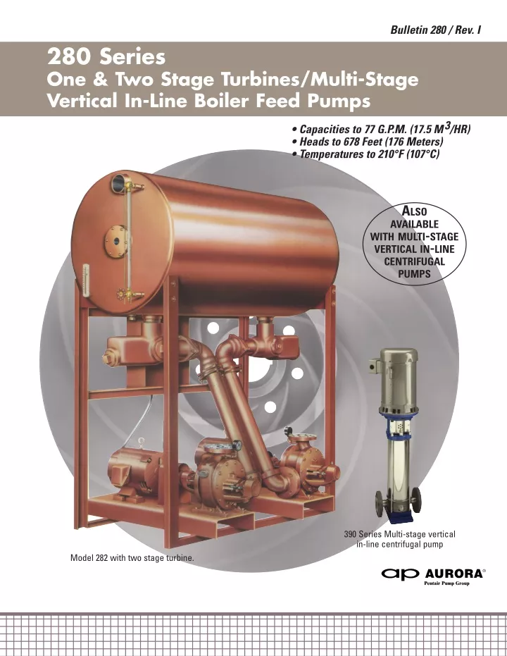
Aurora 280 Boiler feed requirements call for a system that will provide constant service for single or multiple boiler installations.

E N D
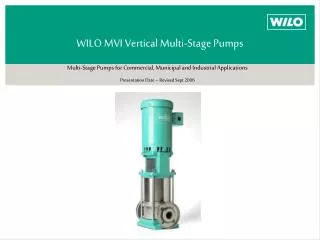
Bulletin 280 / Rev. I 280 Series One & Two Stage Turbines/Multi-Stage Vertical In-Line Boiler Feed Pumps • Capacities to 77 G.P.M. (17.5 M3/HR) • Heads to 678 Feet (176 Meters) • Temperatures to 210°F (107°C) ALSO AVAILABLE WITH MULTI-STAGE VERTICAL IN-LINE CENTRIFUGAL PUMPS 390 Series Multi-stage vertical in-line centrifugal pump Model 282 with two stage turbine.
Aurora 280 Boiler Feed Units Boiler feed requirements call for a system that will provide uninterrupted service for single or multiple boiler installations. Aurora Packaged Systems deliver those values which you need and expect. Quality features include a carbon steel receiver, 3-way valves, and pumps, all completely assembled. Duplex, dual and triplex units do not require any additional floor space than a simplex unit requires. In Aurora’s design, the pumps, bases and piping are mounted beneath the receiver within the support stand. As your heating system grows, the receiver design will allow you to convert from simplex to duplex, dual or triplex construction. Just add pumps and pipe them up! The following pages explain the reasons why AURORA PUMP is able to offer you a modern, packaged, customer proven, feed system. FEATURES 6 3-WAY VALVE provides dependable operation. With a turn of the plug the water flow can be channeled through the strainer or by-passed around the strainer (to allow the strainer to be cleaned), or completely shut off. 1 CARBON STEEL RECEIVER is 3/16” thick to insure long life. Receivers include 2 vents, 2 inlets, drain and connections for additional optional equipment. 2 BRASS FLOAT VALVE with simple lever action replaces water lost due to processing, etc. 7 from receiver to pump. Included are expansion type elbows. COMPLETELY ASSEMBLED PIPING 3 TEMPERATURES TO 210°F water and selected for a minimum capacity of twice the rate of evaporation. 8 ACCESSIBILITY to pump, strainer valve and other components for easier maintenance. All pumps and piping are mounted beneath the receiver within the support stand. 4 BRASS WATER LEVEL GAUGE glass assembly is furnished complete with shut-off valve and protector rods. 9 PUMPS designed for boiler feed applications will handle entrained vapor and air with liquid to eliminate vapor lock. 5INTERCHANGEABLE DESIGN provides future system expansion with receiver connections for up to 3 pumps. Just add pumps and pipe them up. 10 THERMOMETER provides readings from 40°F to 260°F. Optional Pressure Gauges/ A.S.M.E. receivers Electrolytic corrosion inhibitors Inlet “Y” strainers Preheater tube Temperature regulator valve Make-up feeder valve Control panel prewired Electric alternator (Duplex) Special units Galvanized tank Standard Quality Aurora Pumps V.I.P. pump test 3/16” gauge carbon steel receiver with inlet, vent and drain connections 3-Way strainer valves with on-off-by- pass adjustments Piping from receiver to pumps Expansion type suction elbows Gauge glass assembly Mechanical make-up valve Factory assembled Coupling guards Thermometer QUICK REFERENCE 280 SERIES FEATURE SELECTOR page 2
Features ALSO AVAILABLE WITH MULTI-STAGE VERTICAL IN-LINE CENTRIFUGAL PUMPS Model 282 with two stage turbine. page 3
280 Optional Equipment ALSO AVAILABLE WITH MULTI-STAGE VERTICAL IN-LINE CENTRIFUGAL PUMPS page 4
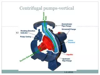
Optional Accessories OPERATION - TURBINE PUMPS The turbine pump derives its name from the many buckets machined into the periphery of the rotating impeller which permits development relatively high pressure in an efficient and economic manner. More pressure is developed within the turbine pump than with a comparable size centrifugal pump. The pumped liquid is directed by the water passage so that it circulates in and out of the buckets many times on its way from the pump inlet to the pump outlet. Additional energy is added to the liquid each time it passes through the buckets so the numerous passes generate a high discharge pressure. The pressure is developed without pulsations. While clearances are used within the turbine pumps, there is no metal to metal contact. Volatile liquids are handled easily because a turbine pump readily handles vapor and air along with the liquid, thus eliminating the possibility of a vapor lock within the pump. Free-flowing and nonlubricatin liquids are handled with a minimum of wear to pump parts because there is no metal to metal contact withing the pump channel. The illustrations indicate the principle used in the handling of the liquid and developing of pressure in a regenerative turbine pump. • Double suction minimizes axial thrust. • Replaceable wearing rings and impellers. • Opposed discharges to balance radial loads (two stage). • Interchangeable packing or mechanical seals. • Large shaft for minimum deflections. • O-rings prevent case leakage on One/Two Stage Turbine Pumps. OPTIONAL BOILER FEED SYSTEM ACCESSORIES 11 MAKE-UP FEEDER VALVE. A) Series 21 for 30, 60 & 100 gallon receivers. B) Series 25 for 200, 250, 350, 500, 750 & 1,000 gallon receivers. 12 125# ASME CODE RECEIVERS of equivalent capacity. Manholes 11” x 15” are included in receiver sizes 350 thru 1,000 gallons. 13 ADDITIONAL PIPE TAPS in receiver. 14 MANHOLE 11” x 15” for receiver capacities of 750 and 1,000 gallons. 15 MAGNESIUM ANODE provides electrolytic corrosion protection. 16 STEAM HEATER PACKAGE consisting of the following: 16A Relief valve 16B Pressure gauge 16C Preheater tube 16D “Y”strainer 16E Temperature regulating valve: a) Low pressure 25T (5-15 P.S.I. steam) WITHOUT pressure reducing attachment. b) High pressure 25PT (50-200 P.S.I. steam) WITH pressure reducing attachment. NOTE: Item 16 components can be provided separately. 17 PREWIRED CONTROL PANEL to all integral H.P. motors includes external reset buttons and hand-off automatic switches. See pages 7, 14 and 15 for details. 18 ELECTRIC ALTERNATOR mounted and wired on duplex. 19 MECHANICAL SEALS for turbine pumps. Mechanical seals are standard on multi-stage vertical in-line pumps. 20 SPECIAL PUMPS (431B, i.e.) 21 DISCHARGE PRESSURE GAUGES ship loose with multi-stage vertical in-line pumps. 22 DUPLEX, DUAL AND TRIPLEX units. See pages 7, 14 and 15. 23 SPECIAL MOTOR DESIGN. 24 GALVANIZED INSIDE AND OUT RECEIVER. of a close channel or page 5
390 Multi-Stage Vertical In-Line Centrifugal Pump Aurora’s line of stainless steel stackable pumps are ideal for high pressure applications which require a minimum amount of floor space. The vertical design is ideal for both new and existing applications. All the pumps’ hydraulic components are of 304 stainless steel. All casings are made of 304 stainless steel. The Nema C motor face and rigid coupling design allows the pump to operate at low noise levels, high efficiency, and long working life with minimal maintenance. Mechanical seals of carbon against silicon carbide, interstage pump bushings of tungsten carbide vs. ceramic, and O-rings of EPDM allow pumps to operate at temperatures to 250˚F. 1 BENEFITS FLOOR SAVING DESIGN: Small base footprint and inline construction minimizes space requirements. 2 COST EFFECTIVE: Stamped Stainless Steel construction provides big pump performance at a small pump cost. 3 LOW OPERATING COST: High hydraulic efficiency as well as excellent NPSH requirements saves money. EASY TO MAINTAIN: Design facilitates quick repair time and in-stock kits for seals and hydraulic components minimize down time. 4 LOW NOISE LEVEL: Superior design limits noise and vibration. KEY FEATURES 5 1 NEMA C-FACE MOTOR REGISTER. 2 ALL METAL RIGID COUPLING. 3 HIGH TEMP/HIGH PRESSURE MECHANICAL SEAL as standard for low maintenance. 4 ALL WETTED COMPONENTS OF AISI 303/304 STAINLESS STEEL for corrosion resistance. DISCHARGE 6 6 5 TUNGSTEN CARBIDE VS CERAMIC BUSHINGS for long life at high temperatures. SUCTION 6 DUCTILE IRON SLIP RING FLANGES for easy piping assembly. page 6
Specifications SIMPLEX-MODEL 281 Mounting Position "A" for Two Stage 4RTL, 5RTL, 6RTL, and 6RATL 110A Turbine Pumps. Mounting Position "C" for Single Stage 4R, 4RA, 5R, and 5RA 110A Turbine Pumps. STANDARD FEATURES: Receiver with make-up valve, sight gauge glass with gauge cock, support legs, 3-way valve, piping, pump, motor, base, coupling, coupling guard, and thermometer. RECOMMENDED OPTIONS: Pump discharge pressure gauge, magnetic starter and on hand-off-automatic switch mounted and wired. DUPLEX-MODEL 282 Mounting Position "A" and "C" for all pump types. For 110A turbines one pump to be Right-handed and one pump to be Left-handed. STANDARD FEATURES: Receiver with make-up valve, sight gauge glass with gauge cock, support legs, 3-way valves, piping, two pumps (one operational and one standby), motors, bases, couplings, coupling guards, and thermometer. RECOMMENDED OPTIONS: Pump discharge pressure gauges, NEMA 1 control panel with two starters, hand-off-automatic switch and selector switch, or alternator, mounted and wired. SIMPLEX-MODEL 281 A B C DUAL-MODEL 282A Mounting Position "A" and "C" for all pump types. For 110A turbines one pump to be Right-handed and one pump to be Left-handed. STANDARD FEATURES: Receiver with make-up valve, sight gauge glass with gauge cock, support legs, 3-way valves, piping, two pumps (that are operational simultaneously), motors, bases, couplings, coupling guards, and thermometer. RECOMMENDED OPTIONS: Pump discharge pressure gauges, NEMA 1 control panel with two starters, hand-off-automatic switch mounted and wired. Two-hand-off-automatic switches for two independently operational pumps are provided. DUPLEX-MODEL 282 A B C DUAL-MODEL 282A A B C TRIPLEX-MODEL 283A Mounting Position "A", "B", & "C" for all pump types. STANDARD FEATURES: Receiver with make-up valve, sight gauge glass with gauge cock, support legs, 3-way valves, piping, three pumps (two operational and one standby), motors, bases, couplings, coupling guards, and thermometer. RECOMMENDED OPTIONS: Pump discharge pressure gauges, NEMA 1 control panel with three starters, two hand-off-automatic switches and two selector switches which allow the following combinations of pumps to operate: 1 & 2, 1 & 3, or 2 & 3, all mounted and wired. TRIPLEX-MODEL 283A A B C page 7
110A Selection Table NOTES: 1) TABLE SELECTIONS ARE FOR INTERMITTENT OPERATION - If system requires continuous operating pumps consult factory for pump selection. 2) Apply firing factor to evaporation rate to obtain actual pump capacity required. 3) MODEL NUMBER EXAMPLE: C4-1/3-4 designates C4 pump size with 1/3 H.P. motor at 4 pole speed. 4 POLES = 1800 RPM MOTOR 6 POLES = 1200 RPM MOTOR 4) For selections not shown, please refer to factory. 281 SIMPLEX 282 DUPLEX BOILER SIZE H.P. EVAP. RATE IN CAPACITY IN GPM GALLONS PUMP (SINGLE BOILER-ONE PUMP) 60 CYCLE (SINGLE BOILER-ONE STANDBY) 60 CYCLE TANK CAPACITY GALLONS 30 30 30 30 30 60 60 60 100 100 100 200 200 250 350 350 350 500 500 750 TANK SIZE INCHES 16x37 16x37 16x37 16x37 16x37 22X37 22X37 22X37 24X51 24X51 24X51 30X65 30X65 36X60 42X60 42X60 42X60 42X84 42X84 48X96 MAKE-UP VALVE SIZE 3/4" NPT 3/4" NPT 3/4" NPT 3/4" NPT 3/4" NPT 3/4" NPT 3/4" NPT 3/4" NPT 3/4" NPT 3/4" NPT 3/4" NPT 1" NPT 1" NPT 1" NPT 1-1/2" NPT 1-1/2" NPT 1-1/2" NPT 1-1/2" NPT 1-1/2" NPT 1-1/2" NPT TANK CAPACITY GALLONS 30 30 30 30 30 60 60 60 100 100 100 200 200 250 350 350 350 500 500 750 TANK SIZE INCHES 16X37 16X37 16X37 16X37 16X37 22X37 22X37 22X37 24X51 24X51 24X51 30X65 30X65 36X60 42X60 42X60 42X60 42X84 42X84 48X96 MAKE-UP VALVE SIZE 3/4" NPT 3/4" NPT 3/4" NPT 3/4" NPT 3/4" NPT 3/4" NPT 3/4" NPT 3/4" NPT 3/4" NPT 3/4" NPT 3/4" NPT 1" NPT 1" NPT 1" NPT 1-1/2" NPT 1-1/2" NPT 1-1/2" NPT 1-1/2" NPT 1-1/2" NPT 1-1/2" NPT 15 20 25 30 40 50 60 70 80 100 125 150 200 250 300 350 400 500 600 700 1.0 1.4 1.7 2.1 2.8 3.5 4.2 4.8 5.5 6.9 8.6 10.7 13.8 17.3 20.7 24.2 27.6 34.5 41.5 48.3 3.9 4.1 4.4 5.0 6.6 7.6 8.5 10.0 11.0 14.0 17.5 21.0 28.0 33.0 38.0 43.0 48.0 57.0 71.0 77.0 50 60 70 80 100 125 150 200 250 300 350 400 500 3.5 4.2 4.8 5.5 6.9 8.6 10.7 13.8 17.3 20.7 24.2 27.6 34.5 7.6 8.5 10.0 11.0 14.0 17.5 21.0 28.0 33.0 38.0 43.0 48.0 57.0 60 60 60 100 100 100 200 200 250 350 350 350 500 22X37 22X37 22X37 24X51 24X51 24X51 30X65 30X65 36X60 42X60 42X60 42X60 42X84 3/4" NPT 3/4" NPT 3/4" NPT 3/4" NPT 3/4" NPT 3/4" NPT 1" NPT 1" NPT 1" NPT 1-1/2" NPT 1-1/2" NPT 1-1/2" NPT 1-1/2" NPT - - - - - - - - - - - - - - - - - - - - - - - - - - - - - - - - - - - - - - - page 8
110A Selection Table NOTES: 1) TABLE SELECTIONS ARE FOR INTERMITTENT OPERATION - If system requires continuous operating pumps consult factory for pump selection. 2) Apply firing factor to evaporation rate to obtain actual pump capacity required. 3) MODEL NUMBER EXAMPLE: C4-1/3-4 designates C4 pump size with 1/3 H.P. motor at 4 pole speed. 4 POLES = 1800 RPM MOTOR 6 POLES = 1200 RPM MOTOR 4) For selections not shown, please refer to factory. 282A DUAL 283A TRIPLEX BOILER SIZE H.P. EVAP. RATE IN CAPACITY IN GPM GALLONS PUMP (TWO BOILERS-TWO PUMPS- LARGE RECEIVER) 60 CYCLE TANK TANK CAPACITY SIZE GALLONS INCHES 30 16x37 60 22x37 60 22x37 60 22x37 100 24x51 100 24X51 100 24X51 200 30X65 200 30X65 250 36X60 250 36X60 350 42X60 500 42X84 500 42X84 750 48X96 750 48X96 1000 48X120 1000 48X120 - - (TWO BOILERS-THREE PUMPS- ONE PUMP STANDBY) 60 CYCLE TANK TANK CAPACITY SIZE GALLONS INCHES - - - - - - - - - - - - - - - - - - - - MAKE-UP VALVE SIZE 3/4" NPT 3/4" NPT 3/4" NPT 3/4" NPT 3/4" NPT 3/4" NPT 3/4" NPT 1" NPT 1" NPT 1" NPT 1" NPT 1-1/2" NPT 1-1/2" NPT 1-1/2" NPT 1-1/2" NPT 1-1/2" NPT 1-1/2" NPT 1-1/2" NPT - - MAKE-UP VALVE SIZE - - - - - - - - - - - - - - - - - - - - 15 20 25 30 40 50 60 70 80 100 125 150 200 250 300 350 400 500 600 700 1.0 1.4 1.7 2.1 2.8 3.5 4.2 4.8 5.5 6.9 8.6 10.7 13.8 17.3 20.7 24.2 27.6 34.5 41.5 48.3 3.9 4.1 4.4 5.0 6.6 7.6 8.5 10.0 11.0 14.0 17.5 21.0 28.0 33.0 38.0 43.0 48.0 57.0 71.0 77.0 - - - - - - - - - - - - - - - - - - - - - - 50 60 70 80 100 125 150 200 250 300 350 400 500 3.5 4.2 4.8 5.5 6.9 8.6 10.7 13.8 17.3 20.7 24.2 27.6 34.5 7.6 8.5 10.0 11.0 14.0 17.5 21.0 28.0 33.0 38.0 43.0 48.0 57.0 - - - - - - - - - - - - - - - - - - - - - - - - - - - - - - - - - - - - - - - 350 350 350 350 350 350 350 500 500 750 750 1000 1000 42X60 42X60 42X60 42X60 42X60 42X60 42X60 42X84 42X84 48X96 48X96 48X120 48X120 1-1/2" NPT 1-1/2" NPT 1-1/2" NPT 1-1/2" NPT 1-1/2" NPT 1-1/2" NPT 1-1/2" NPT 1-1/2" NPT 1-1/2" NPT 1-1/2" NPT 1-1/2" NPT 1-1/2" NPT 1-1/2" NPT page 9
110A Selection Table NOTES: 1) TABLE SELECTIONS ARE FOR INTERMITTENT OPERATION - If system requires continuous operating pumps consult factory for pump selection. 2) Apply firing factor to evaporation rate to obtain actual pump capacity required. 3) MODEL NUMBER EXAMPLE: C4-1/3-4 designates C4 pump size with 1/3 H.P. motor at 4 pole speed. 4 POLES = 1800 RPM MOTOR 6 POLES = 1200 RPM MOTOR 4) For selections not shown, please refer to factory. BOILER SIZE H.P. EVAP. RATE IN CAPACITY IN GPM GALLONS PUMP BOILER OPERATING PRESSURE, PSI MODEL NUMBERS 15# 100# 125# 150# 200# 250# 15 20 25 30 40 50 60 70 80 100 125 150 200 250 300 350 400 500 600 700 1.0 1.4 1.7 2.1 2.8 3.5 4.2 4.8 5.5 6.9 8.6 10.7 13.8 17.3 20.7 24.2 27.6 34.5 41.5 48.3 3.9 4.1 4.4 5.0 6.6 7.6 8.5 10.0 11.0 14.0 17.5 21.0 28.0 33.0 38.0 43.0 48.0 57.0 71.0 77.0 C4-1/3-4 C4-1/3-4 C4-1/3-4 C4-1/3-4 E4-1/3-4 E4-1/3-4 E4-1/3-4 G4-1/2-4 G4-1/2-4 I4-3/4-4 I4-3/4-4 I4-3/4-4 M4-1.5-4 M4-1.5-4 M4-1.5-4 P4-1.5-4 R4-1.5-4 M5-2-4 J6-2-6 K6-2-6 E4T-1.5-4 E4T-1.5-4 E4T-1.5-4 E4T-1.5-4 F4T-2-4 F4T-2-4 G4T-2-4 G4T-2-4 G5-2-4 H5-3-4 H5-3-4 J5-5-4 K5-5-4 L5-7.5-4 L5-7.5-4 G6-10-4 J6-15-4 G6T-10-4 J6T-20-4 K6T-20-4 E4T-1.5-4 E4T-1.5-4 F4T-2-4 F4T-2-4 G4T-3-4 G4T-3-4 I4T-3-4 H5-3-4 H5-3-4 H5-3-4 J5-5-4 K5-7.5-4 L5-10-4 E6T-10-4 E6T-10-4 G6T-10-4 G6T-15-4 J6T-20-4 J6T-20-4 K6T-20-4 F4T-3-4 F4T-3-4 G4T-3-4 G4T-3-4 G4T-3-4 H5-5-4 H5-5-4 H5-5-4 G5T-5-4 H5T-5-4 K5-7.5-4 L5-10-4 D6T-7.5-4 E6T-10-4 G6T-15-4 G6T-15-4 G6T-15-4 J6T-20-4 J6T-20-4 K6T-25-4 D5T-2-4 D5T-2-4 E5T-3-4 E5T-3-4 G5T-5-4 G5T-5-4 G5T-5-4 G5T-5-4 G5T-5-4 H5T-5-4 I5T-7.5-4 D6T-7.5-4 E6T-15-4 G6T-20-4 G6T-20-4 K6T-25-4 K6T-25-4 - - - E5T-3-4 E5T-3-4 G5T-7.5-4 G5T-7.5-4 G5T-7.5-4 G5T-7.5-4 G5T-7.5-4 H5T-7.5-4 H5T-7.5-4 I5T-10-4 I5T-10-4 E6T-20-4 G6T-20-4 - - - - - - - 50 60 70 80 100 125 150 200 250 300 350 400 500 3.5 4.2 4.8 5.5 6.9 8.6 10.7 13.8 17.3 20.7 24.2 27.6 34.5 7.6 8.5 10.0 11.0 14.0 17.5 21.0 28.0 33.0 38.0 43.0 48.0 57.0 E4-1/3-4 E4-1/3-4 G4-1/2-4 G4-1/2-4 I4-3/4-4 I4-3/4-4 I4-3/4-4 M4-1.5-4 M4-1.5-4 P4-1.5-4 P4-1.5-4 R4-1.5-4 M5-2-4 G4T-2-4 G4T-2-4 G5-2-4 G5-2-4 G5-2-4 G5-2-4 J5-5-4 K5-5-4 L5-7.5-4 G6-10-4 G6-10-4 J6-15-4 G6T-10-4 I4T-3-4 I4T-3-4 H5-3-4 H5-3-4 J5-5-4 J5-5-4 K5-7.5-4 L5-10-4 E6T-10-4 G6T-10-4 G6T-10-4 G6T-15-4 J6T-20-4 H5-5-4 H5-5-4 G5T-5-4 G5T-5-4 K5-7.5-4 K5-7.5-4 L5-10-4 D6T-7.5-4 E6T-10-4 G6T-15-4 G6T-15-4 G6T-15-4 J6T-20-4 G5T-5-4 G5T-5-4 G5T-5-4 G5T-5-4 I5T-7.5-4 I5T-7.5-4 D6T-7.5-4 E6T-15-4 G6T-20-4 K6T-25-4 K6T-25-4 K6T-25-4 - H5T-7.5-4 H5T-7.5-4 H5T-7.5-4 H5T-7.5-4 I5T-10-4 I5T-10-4 E6T-20-4 G6T-20-4 - - - - - page 10
390 Selection Table NOTES: 1) TABLE SELECTIONS ARE FOR INTERMITTENT OPERATION - If system requires continuous operating pumps consult factory for pump selection. 2) Apply firing factor to evaporation rate to obtain actual pump capacity required. 3) MODEL NUMBER EXAMPLE: 391-3 / .75 designates 391-3 pump size with .75 H.P. motor. ALL PUMPS ARE 2 POLES OR 3600 RPM MOTOR. 4) For selections not shown, please refer to factory. 281 SIMPLEX 282 DUPLEX BOILER SIZE H.P. EVAP. RATE IN GPM PUMP CAPACITY IN GALLONS (SINGLE BOILER-ONE PUMP) 60 CYCLE (SINGLE BOILER-ONE STANDBY) 60 CYCLE BOILER OPERATION PRESSURE (PSI) TANK CAPACITY GALLONS 30 30 30 30 30 60 60 100 100 100 100 200 200 250 350 350 350 500 500 750 TANK SIZE INCHES 16x37 16x37 16x37 16x37 16x37 22X37 22X37 24X51 24X51 24X51 24X51 30X65 30X65 36X60 42X60 42X60 42X60 42X84 42X84 48X96 MAKE-UP VALVE SIZE 3/4" NPT 3/4" NPT 3/4" NPT 3/4" NPT 3/4" NPT 3/4" NPT 3/4" NPT 3/4" NPT 3/4" NPT 3/4" NPT 3/4" NPT 1" NPT 1" NPT 1" NPT 1-1/2" NPT 1-1/2" NPT 1-1/2" NPT 1-1/2" NPT 1-1/2" NPT 1-1/2" NPT TANK CAPACITY GALLONS INCHES 30 30 30 30 30 60 60 100 100 100 100 200 200 250 350 350 350 500 500 750 TANK SIZE MAKE-UP VALVE SIZE 3/4" NPT 3/4" NPT 3/4" NPT 3/4" NPT 3/4" NPT 3/4" NPT 3/4" NPT 3/4" NPT 3/4" NPT 3/4" NPT 3/4" NPT 1" NPT 1" NPT 1" NPT 1-1/2" NPT 1-1/2" NPT 1-1/2" NPT 1-1/2" NPT 1-1/2" NPT 1-1/2" NPT 15# 2.0 2.4 2.8 3.2 4.0 4.8 5.6 6.4 7.2 8.7 10.7 12.7 16.7 20.6 24.6 30.8 34.8 42.7 50.7 58.6 100# 125# 150# 175# 4.1 4.3 4.5 4.7 4.9 5.1 5.3 5.5 6.1 6.3 6.8 7.1 7.6 7.9 8.4 8.7 9.2 9.5 10.8 11.1 12.8 13.1 14.4 15.1 18.8 19.0 22.7 23.0 26.7 27.0 32.9 3.4 36.9 37.4 44.8 45.3 52.8 53.2 60.7 61.2 200# 250# 5.0 5.4 5.8 6.2 7.0 7.8 8.6 9.4 10.2 11.8 13.8 15.8 19.7 23.7 30.5 34.5 38.0 46.4 64.0 71.9 15 20 25 30 40 50 60 70 80 100 125 150 200 250 300 350 400 500 600 700 1.0 1.4 1.7 2.1 2.8 3.5 4.2 4.8 5.5 6.9 8.6 10.7 13.8 17.3 20.7 24.2 27.6 34.5 41.5 48.3 4.6 5.0 5.4 5.8 6.6 7.4 8.2 9.0 9.8 11.3 11.6 13.3 13.6 15.3 15.5 19.3 19.5 23.2 23.5 27.2 27.4 33.8 34.2 37.8 38.1 45.7 46.1 53.6 63.2 61.6 71.1 4.8 5.2 5.6 6.0 6.8 7.6 8.4 9.2 10.0 5.5 5.9 6.3 6.7 7.4 8.2 9.0 12.9 13.7 15.3 15.7 17.7 21.7 27.2 31.1 33.6 34.7 57.5 65.4 73.3 16X37 16X37 16X37 16X37 16X37 22X37 22X37 24X51 24X51 24X51 24X51 30X65 30X65 36X60 42X60 42X60 42X60 42X84 42X84 48X96 page 11
390 Selection Table NOTES: 1) TABLE SELECTIONS ARE FOR INTERMITTENT OPERATION - If system requires continuous operating pumps consult factory for pump selection. 2) Apply firing factor to evaporation rate to obtain actual pump capacity required. 3) MODEL NUMBER EXAMPLE: 391-3 / .75 designates 391-3 pump size with .75 H.P. motor. ALL PUMPS ARE 2 POLES OR 3600 RPM MOTOR. 4) For selections not shown, please refer to factory. 282A DUAL 283A TRIPLEX (TWO BOILERS-THREE PUMPS- ONE PUMP STANDBY) 60 CYCLE TANK TANK CAPACITY SIZE GALLONS INCHES - - - - - 350 42X60 350 42X60 350 42X60 350 42X60 350 42X60 350 42X60 350 42X60 500 42X84 500 42X84 750 48X96 750 48X96 1000 48X120 1000 48X120 - - BOILER SIZE H.P. EVAP. RATE IN GPM PUMP CAPACITY IN GALLONS (TWO BOILERS-TWO PUMPS- LARGE RECEIVER) 60 CYCLE TANK TANK CAPACITY GALLONS INCHES 30 16x37 60 22X37 60 22X37 60 22X37 100 24X51 100 24X51 100 24X51 200 30X65 200 30X65 250 36X60 250 36X60 350 42X60 500 42X84 500 42X84 750 48X96 750 48X96 1000 48X120 1-1/2" NPT 1000 48X120 1-1/2" NPT - - - - BOILER OPERATION PRESSURE (PSI) MAKE-UP VALVE SIZE 3/4" NPT 3/4" NPT 3/4" NPT 3/4" NPT 3/4" NPT 3/4" NPT 3/4" NPT 1" NPT 1" NPT 1" NPT 1" NPT 1-1/2" NPT 1-1/2" NPT 1-1/2" NPT 1-1/2" NPT 1-1/2" NPT MAKE-UP VALVE SIZE - - - - - 1-1/2" NPT 1-1/2" NPT 1-1/2" NPT 1-1/2" NPT 1-1/2" NPT 1-1/2" NPT 1-1/2" NPT 1-1/2" NPT 1-1/2" NPT 1-1/2" NPT 1-1/2" NPT 1-1/2" NPT 1-1/2" NPT - - SIZE 15# 2.0 2.4 2.8 3.2 4.0 4.8 5.6 6.4 7.2 8.7 10.7 12.7 16.7 20.6 24.6 30.8 34.8 42.7 50.7 58.6 100# 125# 150# 175# 4.1 4.3 4.5 4.7 4.9 5.1 5.3 5.5 6.1 6.3 6.8 7.1 7.6 7.9 8.4 8.7 9.2 9.5 10.8 11.1 12.8 13.1 14.4 15.1 18.8 19.0 22.7 23.0 26.7 27.0 32.9 3.4 36.9 37.4 44.8 45.3 52.8 53.2 60.7 61.2 200# 250# 5.0 5.4 5.8 6.2 7.0 7.8 8.6 9.4 10.2 11.8 13.8 15.8 19.7 23.7 30.5 34.5 38.0 46.4 64.0 71.9 15 20 25 30 40 50 60 70 80 100 125 150 200 250 300 350 400 500 600 700 1.0 1.4 1.7 2.1 2.8 3.5 4.2 4.8 5.5 6.9 8.6 10.7 13.8 17.3 20.7 24.2 27.6 34.5 41.5 48.3 4.6 5.0 5.4 5.8 6.6 7.4 8.2 9.0 9.8 11.3 11.6 13.3 13.6 15.3 15.5 19.3 19.5 23.2 23.5 27.2 27.4 33.8 34.2 37.8 38.1 45.7 46.1 53.6 63.2 61.6 71.1 4.8 5.2 5.6 6.0 6.8 7.6 8.4 9.2 10.0 5.5 5.9 6.3 6.7 7.4 8.2 9.0 12.9 13.7 15.3 15.7 17.7 21.7 27.2 31.1 33.6 34.7 57.5 65.4 73.3 - - - - - - - - - page 12
390 Selection Table NOTES: 1) TABLE SELECTIONS ARE FOR INTERMITTENT OPERATION - If system requires continuous operating pumps consult factory for pump selection. 2) Apply firing factor to evaporation rate to obtain actual pump capacity required. 3) MODEL NUMBER EXAMPLE: 391-3 / .75 designates 391-3 pump size with .75 H.P. motor. ALL PUMPS ARE 2 POLES OR 3600 RPM MOTOR. 4) For selections not shown, please refer to factory. BOILER SIZE H.P. EVAP. RATE IN GPM PUMP CAPACITY IN GALLONS BOILER OPERATING PRESSURE, PSI MODEL NUMBERS BOILER OPERATION PRESSURE (PSI) 15# 100# 125# 150# 175# 200# 250# 15# 2.0 2.4 2.8 3.2 4.0 4.8 5.6 6.4 7.2 8.7 10.7 12.7 16.7 20.6 24.6 30.8 34.8 42.7 50.7 58.6 100# 125# 150# 175# 4.1 4.3 4.5 4.7 4.9 5.1 5.3 5.5 6.1 6.3 6.8 7.1 7.6 7.9 8.4 8.7 9.2 9.5 10.8 11.1 12.8 13.1 14.4 15.1 18.8 19.0 22.7 23.0 26.7 27.0 32.9 3.4 36.9 37.4 44.8 45.3 52.8 53.2 60.7 61.2 200# 250# 5.0 5.4 5.8 6.2 7.0 7.8 8.6 9.4 10.2 11.8 13.8 15.8 19.7 23.7 30.5 34.5 38.0 46.4 64.0 71.9 15 20 25 30 40 50 60 70 80 100 125 150 200 250 300 350 400 500 600 700 1.0 1.4 1.7 2.1 2.8 3.5 4.2 4.8 5.5 6.9 8.6 10.7 13.8 17.3 20.7 24.2 27.6 34.5 41.5 48.3 4.6 5.0 5.4 5.8 6.6 7.4 8.2 9.0 9.8 11.3 11.6 13.3 13.6 15.3 15.5 19.3 19.5 23.2 23.5 27.2 27.4 33.8 34.2 37.8 38.1 45.7 46.1 53.6 63.2 61.6 71.1 4.8 5.2 5.6 6.0 6.8 7.6 8.4 9.2 10.0 5.5 5.9 6.3 6.7 7.4 8.2 9.0 12.9 391-3/.75 13.7 391-3/.75 15.3 391-3/.75 391-10/3 15.7 391-3/.75 17.7 392-3/1 21.7 392-3/1 27.2 392-3/1 31.1 392-4/1.5 392-10/5 33.6 393-3/3 34.7 393-3/3 57.5 393-3/3 65.4 393-3/3 393-10/7.5 393-10/7.5 393-12/10 394-9/20 393-14/15 394-12/25 73.3 393-3/3 393-10/7.5 393-12/10 393-14/15 394-9/20 391-3/.75 391-3/.75 391-3/.75 391-3/.75 391-3/.75 391-3/.75 391-3/.75 391-8/2 391-8/2 391-8/2 391-8/2 391-8/2 391-8/2 391-9/2 391-9/2 391-9/2 391-9/2 391-9/2 391-10/3 391-10/3 391-10/3 391-10/3 391-10/3 391-11/3 391-11/3 391-13/3 392-10/5 392-10/5 392-11/5 392-11/5 392-13/5 391-11/3 391-13/3 391-11/3 391-13/3 391-11/3 391-13/3 391-11/3 391-13/3 391-11/3 391-13/3 391-13/3 391-13/3 391-13/3 391-15/5 391-13/3 391-15/5 391-13/3 391-15/5 391-13/3 391-15/5 391-11/5 392-13/5 392-11/5 392-13/5 392-13/5 392-13/5 392-13/5 392-15/5 392-16/7.5 393-14/15 392-15/5 392-16/7.5 393-15/10 393-14/15 391-15/5 391-18//5 391-15/5 391-15/5 391-18/5 391-15/5 391-18/5 391-15/5 391-18/5 391-15/5 391-18/5 391-15/5 391-18/5 391-16/5 393-14/15 391-16/5 393-14/15 392-15/5 393-14/15 392-15/5 393-14/15 392-15/5 393-14/15 392-15/5 393-14/15 391-18/5 392-8/3 392-9/3 392-9/3 392-9/3 393-7/7.5 393-8/7.5 393-10/7.5 393-12/10 393-12/10 393-14/15 393-7/7.5 393-10/7.5 393-10/7.5 393-12/10 393-12/10 394-12/25 393-8/7.5 393-10/7.5 393-12/10 393-12/10 393-15/15 394-12/25 394-10/2 394-12/25 page 13
Standard Equipment and Engineering F APPROX. A M M SIGHT GLASS [2] P NPT [1] L NPT THERMOMETER [2] S NPT B DIA. [1] 1-1/4 NPT [1] 3 NPT [1] 1 NPT (DRAIN) OPTIONAL CONTROLLER W C N E DISCHARGE DISCHARGE DISCHARGE COUPLING GUARD R 2 (51) G J J [4] 5/8 (16) DIA. MOUNTING HOLES 10 H K K 110A Turbine Pumps RECEIVER 3-WAY CAPACITY GALLONS 30 60 100 200 250 350 500 750 1000 VALVE SIZE 1-1/4 1-1/4 1-1/4 2* 2* 3** 3 3 3 A B C E F G H J K L M N P S R 37 37 51 65 60 60 84 96 120 16 22 24 30 36 42 42 48 48 42.19 49.69 59.69 77.19 80.19 80.19 80.19 88.19 88.19 34 38.5 47.5 62 62 59 59 64 64 44 44 58 72 67 67 91 103 127 14.25 20.38 21.25 26.25 28.38 36.75 37.38 45.5 45.5 15.75 21.88 22.75 27.75 29.88 38.25 38.88 47 47 9 9 11 17 17 17 17 17 17 15.5 15.5 21 25.5 25.5 25.5 28.5 35.5 47.5 3/4 3/4 3/4 1 1 1-1/2 1-1/2 1-1/2 1-1/2 14.5 15 20.5 26.5 26.5 26.5 38.5 40 52 40 47 57 74 77 76 76 85 85 2 2 2 3 3 3 3 3 3 2 2 3 3 3 3 3 3 3 7.81 4.75 4.31 10.81 9.81 5.63 10.5 1.25 1.25 * 3” with pump sizes D6T and E6T ** 2” with pump sizes J5, K5 and L5. LIMITATIONS MAXIMUM DISCHARGE PRESSURE MAXIMUM TEMP. LIMIT ON PUMP SUCTION RECEIVER ASSEMBLY PART Receiver 3-Way Valve Body 3-Way Valve Strainer Float Valve Gauge Glass Fitting Base and Supports MAXIMUM INTERNAL 5 P.S.I.G. Short Surges Only* MAKE-UP VALVE** MATERIAL 3/16” CARBON STEEL Cast Iron ASTM A48-64 Brass Brass ASTM B-36 Brass ASTM B-36 Commercial Steel 3/4” NPT 22.5 G.P.M. 1” NPT 45 G.P.M. 1-1/2” NPT 87 G.P.M. 250 P.S.I.G. 210˚F * This is a vented system and pressure ratings are for short surges only. **Make-up valve limitation based on 40 P.S.I. utility water pressure. Notes: 1. Dimensions and weights are approximate. 2. All dimensions are in inches (mm) and may vary ± .50”. 3. Optional Controller may be mounted on end of unit if space deems it to be necessary. 4. Not for construction purposes unless certified. page 14
Standard Equipment and Engineering F APPROX. A P NPT SIGHT GLASS M M (1) P NPT THERMOMETER (1) L NPT B DIA. (2) S NPT VENTS (1) 1 1/4" NPT (1) 1" NPT DRAIN OPTIONAL CONTROLLER (1) 3" NPT C N E R DISCHARGE DISCHARGE J J G (4) 5/8" DIA. MOUNTING HOLES. 10 H K K 390 Multi-Stage Vertical In-Line Pumps RECEIVER 3-WAY CAPACITY GALLONS 30 60 100 200 250 350 500 750 1000 VALVE SIZE 1-1/4 1-1/4 3 3 3 3 3 3 3 A B C E F G H J K L M N P S R 37 37 51 65 60 60 84 96 120 16 22 24 30 36 42 42 48 48 69.19 76.69 86.69 101.19 104.19* 116.19* 116.19* 124.19* 124.19* 61 65.5 74.5 86 86 95 95 100 100 44 44 58 72 67 67 91 103 127 14.25 20.38 21.25 26.25 28.38 36.75 37.38 45.5 45.5 15.75 21.88 22.75 27.75 29.88 38.25 38.88 47 47 9 9 11 17 17 17 17 17 17 15.5 15.5 21 25.5 25.5 25.5 28.5 35.5 47.5 3/4 3/4 3/4 1 1 1-1/2 1-1/2 1-1/2 1-1/2 14.5 15 20.5 26.5 26.5 26.5 38.5 40 52 67 74 84 98 101 112 112 121 121 2 2 2 3 3 3 3 3 3 2 2 3 3 3 3 3 3 3 .13 1.06 2.06 1.13 .06 .38 .06 .5 .5 * “C” DIMENSIONS OVER 103 WILL REQUIRE SPECIAL SHIPPING ARRANGEMENTS. MATERIALS OF CONSTRUCTION 110A TURBINE PUMPS PUMP PART Casing Covers Channel Rings Impeller Shaft Center Spacer Packing MATERIAL Cast Iron ASTM A48-64 Cast Iron ASTM A48-64 Cast Iron ASTM A48-56 Bronze ASTM B62-63 Stainless Steel AISI-416 Cast Iron ASTM A48-56 Interwoven, T.F.E. impregnated acrylic die molded, diagonally cut Optionally available Mechanical Seals 390 MULTI-STAGE VERTICAL IN-LINE CENTRIFUGAL PUMPS PUMP PART MATERIAL Upper Casing Stainless Steel AISI 304 wetted & ASTM 48 Class 35 Lower Casing Stainless Steel AISI 304 wetted with Iron Flange Rings Diffusers Stainless Steel AISI 304 Impeller Stainless Steel AISI 304 Shaft Stainless Steel AISI 303 Pump Sleeve Stainless Steel AISI 304 Pump Bushings Tungsten Carbide vs Aluminum Oxide Ceramic O-rings EPDM Mechanical Seal Carbon vs Silicon Carbide Faces with EPDM Elastomers & AISI 316 SS metals Notes: 1. Dimensions and weights are approximate. 2. All dimensions are in inches (mm) and may vary ± .50”. 3. Optional Controller may be mounted on end of unit if space deems it to be necessary. 4. Not for construction purposes unless certified. page 15
Engineering Specifications Furnish and install as shown on the plans, one Aurora Pump Model Number....(Simplex) (Duplex) (Dual) (Triplex) packaged Boiler Feed System consisting of.....Gallon receiver of carbon steel with flat heads, (turbine pump(s), (multi-stage vertical in-line centrifugal pump(s), .... horsepower, ..... R.P.M. motor(s), 3-way strainer valve(s), steel base and supports, and all necessary suction piping factory installed. The system shall be suitable for returning.....G.P.M. at a pressure of ......P.S.I. for 210˚F water to supply a ..... H.P. boiler. TURBINE PUMPS: Each pump shall be the APCO bronze fitted turbine type. The pump casing(s) shall be vertically split. The pump covers shall be of the removable channel ring design to permit replacement of the channels only and shall incorporate the bearing arms and stuffing boxes for (packing) (mechanical seals). The pump(s) shall be flexibly coupled to the motor(s). MULTI-STAGE VERTICAL IN-LINE CENTRIFUGAL PUMPS: Each pump shall be in Multi-Stage Vertical In-Line Centrifugal Pump. Each pump shall be constructed with 304 Stainless Steel impellers and diffusers, a high temperature mechanical seal with carbon vs Silicon Carbide, EPDM elastomers through out, Tungsten Carbide against Ceramic pump bushings and a Cast Iron motor bracket. Flanges will be Ductile or cast Iron in Slip Ring (and isolated for liquid). TURBINE OR MULTI-STAGE VERTICAL IN-LINE CENTRIFUGAL PUMPS: The pump(s) shall be mounted within the support stand on a common steel base. Coupling guard(s) will be provided. Suction piping between the receiver and pump(s) shall be factory assembled with expansion type elbows to relieve pipe strain and vibration and 3-way strainer valve(s) with removable brass strainer. The strainer valve plug must be so designed that by turning the plug the liquid flow may be channeled in tow directions - through the strainer housing or by-pass around the strainer directly into the pump - or be completely shut off. The receiver shall contain all necessary openings for float operated automatic make-up water feeder, water level sight glass with shut-off valves, thermometer, and in simplex units, a plugged suction opening for a future pump shall be provided, to easily convert a simplex unit to a duplex or dual unit. The receiver shall be 3/16” carbon steel and shall be mounted on structural steel legs attached to the pump base. Threaded inlets shall be provided at the top of both tank heads. Two vents shall be provided and also a 1” drain. Motors shall be open drip-proof for (230/460 volt, 3 phase) (115/230 volt, 1 phase) 60 Hertz current, built in a standard NEMA frame. OPTIONAL: Magnetic starters with overload and under voltage protection shall be mounted and wired to the pump motors, (3 phase, 1/3 H.P motors or less). On Simplex units, the starters shall be in a general purpose enclosure. On Duplex, Dual and Triplex units, magnetic starters shall be panel mounted in a NEMA 1 enclosure. Reset buttons shall be provided outside the box. On Duplex and Triplex units, transfer switches to provide standby pump operations shall be mounted and wired in the panel. The transfer switch is not required on Dual units. An alternator (will) (will not) be provided on Duplex models in lieu of a selector switch. AP-280 / Rev. I 3/04 PRINTED IN U.S.A. NOTE: Aurora Pump reserves the right to make revisions to its products and their specifications, and to this bulletin and related information, without notice. MARKETING & SALES: 800 AIRPORT ROAD • NORTH AURORA, ILLINOIS U.S.A. • 60542 PHONE: (630) 859-7000 U.S.A./CANADA FAX: (630) 859-7060 WORLDWIDE FAX: (630) 859-1226 AURORA MFG. PLANT: 800 AIRPORT ROAD • NORTH AURORA, ILLINOIS U.S.A. • 60542 SALES OFFICES IN ALL MAJOR CITIES AND COUNTRIES Refer to “Pumps” in yellow pages of your phone directory for your local Distributor — Your Authorized Local Distributor — ISO9001REGISTEREDQUALITYSYSTEM